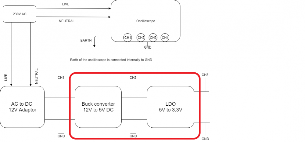
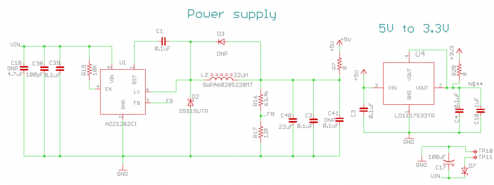
the attached circuit diagram is of my power supply. It converts input 12V DC into 5V DC and then 3.3V DC with linear regulator. I have highlighted it in red color in the block diagram.
So current situation is, whatever noise is there on 12V input voltage shows up on 5V and 3.3V. how do i filter this? how do i improve my design to get clean 5V and 3.3V even with a noisy 12V input. If i use clean power supply 12v, i am getting best results.But i cant give 12V clean power supply to everyone. Customers can pick up any noisy power supply and it should work with my design.
Below i am attaching two waveforms showing, Yellow as 12V , Blue is 5V and Pink is 3.3V.
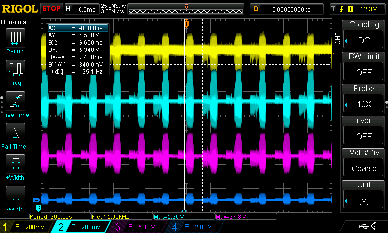
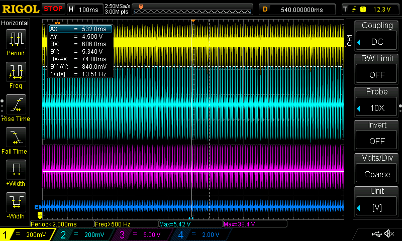
If you look at the waveforms, the noise appearing on 12V is carried on to the 3.3V. i was assuming LDO will at least attenuate it more but, it is very high.
how do i get rid of this, what ill have to change or add in my design to improve it?
Note: Input 12V Dc power supply used is a 220V AC to 12V DC adapter.
In reply to Remove noise from 12V supply voltage by Bradyen
hi Bradyen,
thanks for your reply. yes ill try LC filter it looks a better choise.
Yes the oscilloscope was properly grounded and calibraded and i assured that it is not picking up any random Ac noise. the noise which you see is from the 12V wall adaptor i am using.
since i am designing the circuit to work with noisiest power supply, i purposely selected this cheap chinese SMPS wall adaptor whiich has lot of noise and ripple on the output.
Yes i am using cobination of electrolaytic and ceramic SMD capacitors taking care of the ESR.
can you advise me some LC filter to filter out this noise?
Since it is Dc ideally i should cutt of at say 1Hz but thats not possible. so which frquencies i should target ?
what should be my cuttoff and since its a power supply and my circuit draws 100mA (at 12V) from it, I should select values of L and C such that enough current can flow without affecting performance of filter. correct?
can you suggest something on this?

Your measurement is absolutely wrong.
Noise and ripple of a power supply unit is a form of AC signal i.e It has the frequency, it changes polarity over time, very fast frequency is a noise and the switching frequency is the ripple voltage. Ripples are responsible for the switching of capacitors. On each switching cycle, its charge and discharge and you get a mean value across the output.
To measure noises and ripple of a power supply unit you need to do few things. At first, you should make the actual setup.
You need the pigtail method. It is a proper technique. I personally prefer to use this.
Then change the scope setting. You are measuring AC. Not DC. Change the Probe mode to 1x and also in the scope.
Measure directly across the last output capacitor as per your PCB Board design on a specific power path.
Here is the reference image -

Carefully look, the measurement is taken across the output capacitor.
The waveform is showing a sinewave. the sinewave amplitude (pk-pk) is a ripple. The distortion between the sinewave is the noise.
After getting the perfect result I would like to ask a few more things.

Bradyen
Joined August 14, 2018 44Tuesday at 03:25 PM
For Linear regulators noise is a pretty common problem. But how much noise are you are getting? Your scope shows some values whcih I cant make sense off. Normally a noise value of 20mV or less is tollerable with regulator circuits. But yours look way more crazy probably because there is no filter circuit. You can try the following points to improve from here
1.Add an LC filter to the 12V input voltage, this should filter the noise form your input voltage. Make sure the L is a big choke that can handle high frequency noise.
2. Use low ESR capacitor for the input filter (C18,C38,C39). Try this as last option.
3. Make sure you are using a combintaon of electrolytic and ceramic capacitor for the filter, probably C18,C38 should be electrolytic and C39 should be ceramic
4. Make sure your scope mains is grounded and scope is calibrated properly. Because the waves look bizzare for a 12V input supply may be the scope is picking up some other noise. Try connecting both the probes togather to check if you are getting a clear signal
Also I am not sure what is your source for 12V is it an SMPS or wall adapter? Does it have isolation? Also what was the pure 12V that you used to test the circuit earlier was it a battery?