Hello everyone!
I need assistance with safety distress circuit design for Nurse Call System.
Following is system connection:
1.Nurse Call Station with LCD screen
2.Main panel- connection board
3.Bed Head Console
-Nurse Call Station & Bed Head Console connected to main panel - connection board.
Following picture describe Inputs of Bed Head Console:
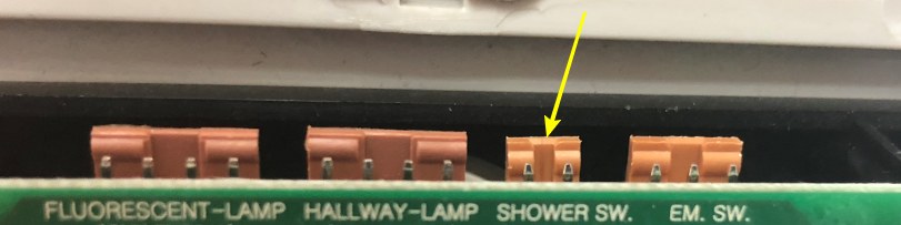
Mentioned "SHOWER SWITCH" is the input I need safty design for.
At first operation, patient pulls emergancy switch and trigger the alarm at Nurse Call Station, indicating room & bed number stress call.
Problem occurs with second trigger, patient pulls emergancy switch again and disabled the alarm at Nurse Call Station side.
I resolved trigger disable safty with a letch relay type DS2E-ML2-DC24V.
Second stage, is to disable latch relay and disabling the alarm system from "SHOWER SWITCH" again at the same time, with another cancellation button.
For that purpose I tried using relay timer type 24V FRM01 Multifunctional Relay Module Loop Delay Timer Switch Self-locking,
With no luck.
According to my tests, it seems that I need more components or a different design.
Thank you in advance.

Following scheme describe my inquiry for IC :

Technical requirements IC:
1.SW1 trigger input 1&2 of IC and sends momentry pulse (1 sec) N.O. type to output ports 7&8 of IC.
2.Inputs 1&2 must be "latch" type - SW1 is disable after triggering.
3.SW2 is enabled only after SW1 is triggerd (latch mode).
4.SW2 release SW1 with momentary pulse (non-latch).
5.When SW2 is triggered, IC starts selectable cycle time of 5-10 sec.
6.At the END of cycle time, momentry pulse (1 sec) N.O. type recieved at ports 7&8.
Thank you
In reply to Following scheme describe my by Roy
There is no single IC that can work as per your requirment. You can either create a complex circuit using JK flip-flop and then use a momentory latching circuit on the input. But again you will need a timer IC on the output along with this for your delay requirments.
The best way to go from here is to use a microcontroller.

Violet
Joined August 16, 2018 42Thursday at 11:31 AM
You question is really confusing since not many proplr could understand the application you are using the circuit for.
May be you should try reframing the question with simple logic instead of using the actual application words