I saw an LM358 circuit while browsing the video. Here is a brief copy of the circuit description:
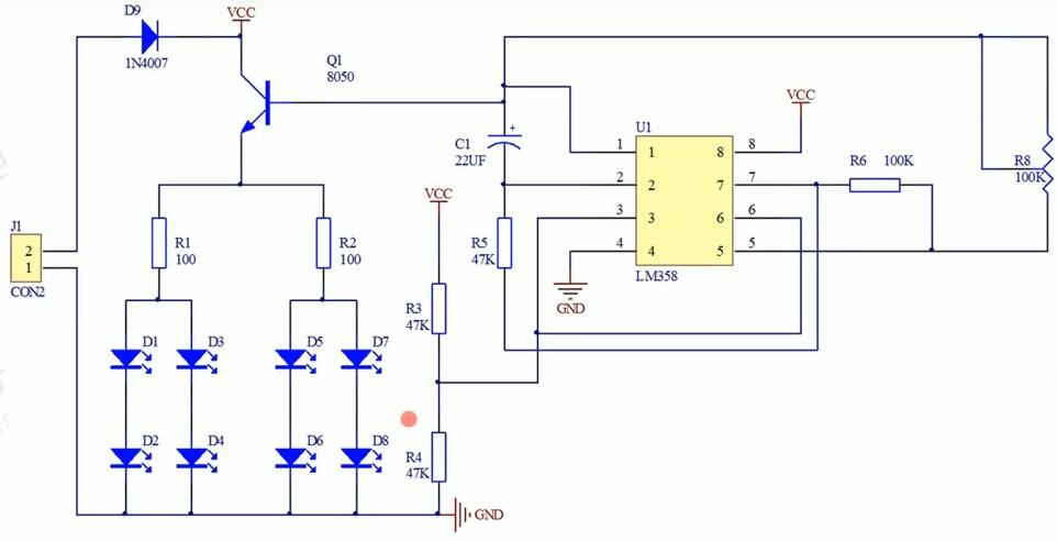
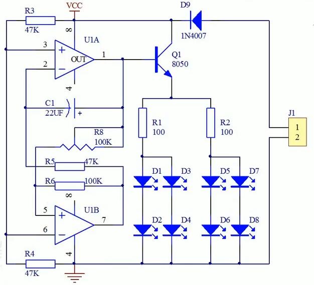
The core of the breathing light circuit is LM358, which includes two independent, high-gain, internal frequency-compensated dual operational amplifiers, which together with the external circuit form a relatively accurate bistable circuit.

Here, R3 and R4 constitute the reference divided voltage of the dual operational amplifier 6V, R6 is the operational amplifier feedback resistance, and C1, R5, R6, and R8 determine the frequency of the control breathing lamp. This LM358 circuit is adjusted by potentiometer R8.

After reading this, I get 3 questions:
1. How can I add more LEDs?
2. Can this capacitor be used with a patch?
3. Is the potentiometer R8 package included in the library?
Anyone can help? Thank you in advance.


Sourav Gupta
Joined February 12, 2018 696Monday at 02:11 PM
1. You need to change the transistor, R1 and R2.
2. Yes it can. That would be costly.
3. I dont understand, what library? It is a schematic. What kind of libraries are you reffering?