Hello, this is my first post here on this site. I hope to keep this as simple as possible. ive been designing PCB on my and i would be real greatful if anyone would look over my design and tell me if anything is wrong or that could go wrong.
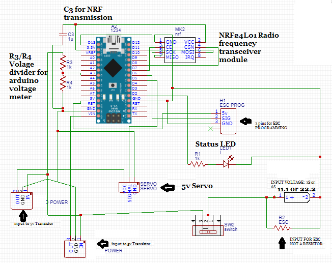
Synoposis: rc sled RECEIVER board through RF frequency (NRF24l01) and arduino nano. Powering 1 BLDC with ESC and 5v servo.
NOTE: the Resistance and capacitance value shown is NOT what i will be using, ive done some calculations to figure out optimal values required.
Using the arduin nano to control my radio frequency transeiver module as a receiver module. my power source will be either a 3s or a 6s battery to power the entire circuit. im using 2 transistors that will tolerate the input voltage of the 6s battery and output only 5v, one to power the arduino, one to power the servo, all grounds are tied together, to drive the main sled motor (single propeller) im using a 30Amp programmable ESC. 1 servo being driven by the arduino but not powered by the arduino 5v but a seperate transistor which should provide the current required.
R3/R4 connects directly to the battery, sends a signal to the arduino (4.5v or less) to detect battery life.
C3 is there because it seems like the 3.3v pin of the arduino doesnt provide enough current during transmission. works close range without C3 but need it for longer distange.
Simple status LED in there, will probably change to RGB led.
R2(bottom right), is actually not a resistor, its suppose to be the input voltage for the ESC. i just enlarged the holes and made the wiring path of the pcb thicker when desiging the PCB.
Thanks for the feedback, hoping this would be an all in 1 receiving module with 1 motor and 1 servo (rc car style) but for a sled.