
While building circuits many times we need to generate sounds like a musical sound or some kind of alerting sound. Instead of building complex circuitry, we have some use full IC to produce the sound like UM66, UM3561 etc. While UM66 have a limitation of generating only one sound, we have UM3561 which is very useful and can generate four types of sound i.e. Police siren, Fire Brigade siren, Ambulance Siren and Machine Gun siren. UM3561 is very handy when we need to generate these kinds of alerting sounds and it’s very easy to use this IC.
UM3561 IC
UM3561 is a CMOS LSI IC which can generate four types of sound as we discussed. It is generally used in alarms and toys. It is a low cost and low powered 8 pin IC. It has inbuilt oscillators and circuitry to produce the sounds, and only require one external resistor. This external resistor is connected between PIN 7 and PIN 8, and used to control the frequency of oscillations. A variable resistor can be used to change the frequency of sound or a 220K fixed resistor works well if you don’t want to change the frequency.
UM3561 works in the range of 3-5 volts, voltage higher than 5V can damage the IC, so if we are using it with other circuit or using a high voltage source, a Zener diode must be connected, to protect the IC. The output generated by the IC is not sufficient to drive a 8ohm small speaker, so to amplify the output of the IC, a transistor must be used at the output (PIN 3).
UM3561 Pin diagram and Pin description is given below, taken from its Datasheet:
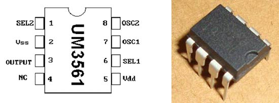
Pin No. | Symbol | Description |
1 | SEL2 | Sound Effect Selection Pin No.2 |
2 | Vss | Ground |
3 | Output | OUTPUT |
4 | NC | Internal Testing Pin : Leave Open for Normal Operations |
5 | Vdd | Positive of Power Supply |
6 | SEL1 | Sound Effect Selection Pin No.1 |
7 | OSC1 | External Oscillator Terminal 1 |
8 | OSC2 | External Oscillator Terminal 2 |
We can play four sound by using its 2 sound Effect selection Pins (SEL 1 and SEL 2), like SEL 1 and SEL 2 should be kept open to produce the Police Siren sound. Below is the table for 4 Playing modes, you can produce whatever sound you want.
SEL 1 | SEL 2 | Sound Effect |
NC | NC | Police Siren |
Vdd | NC | Fire Brigade Siren |
Vss | NC | Ambulance Siren |
X | Vdd | Machine Gun |
NC: No Connection
X: Don’t Care
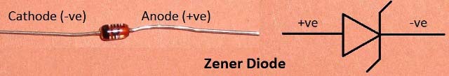
Zener Diode
Zener Diode is just like the other diodes, with only one difference. All the diodes allow flow of current in only one direction (forward), but Zener diode can allow current in reverse direction if the voltage goes beyond a certain limit. This voltage is called Breakdown Voltage or Zener Knee voltage. So this property of Zener diode protects the UM3561 IC by preventing higher voltage supply to it.
Components
- UM3561 IC
- Resistors 10K, 150K
- Variable Resistor 100K
- Transistor BC547
- Zener Diode 3.3v
- Speaker 8ohm
- 3 Push Button Switch
- Battery 9v
Circuit Diagram and Explanation

- 100k variable resistor with 150K resistor is used between PIN 7 and 8 to change the frequency of oscillation on board. We can change the frequeccy by rotating the knob of variable resistor.
- 8ohm speaker is used with NPN transistor BC547 to produce the sound, as we know UM3561 output is not enough to drive a speaker so we have used transistor to amplify the output.
- 3 Push buttons are used to produce 3 different sounds. When no button is pressed (SEL 1 and SEL 2 open), Police siren sound is generated; when Button S1 is pressed (SEL 1 Grounded-Vss and SEL 2 Open), Ambulance Siren is generated; when Button S2 is pressed (SEL 1 HIGH-Vdd and SEL 2 Open), Fire Brigade Siren is generated; when Button S3 is pressed (SEL 1 Open and SEL 2 HIGH-Vdd), Machine gun Siren is generated.
- As we have used 9v battery, so we have used Zener Diode (3.3v) for voltage regulation, because IC can be damaged by directly applying voltage higher than 5v.

Hi buddy there is basic flaw in circuit. U should be careful while drawing the circuit. With some basic mistakes just as in your circuit the beginners will get disheartened when there ckt doesn't work. The zener diode is connected directly to the 9 volt supply. There should be a resistence of 1K. in series to the supply. Thanks.