

In this project let us develop an LED Strobe light circuit using the popular 555 timer IC. A strobe light or a stroboscopic lamp is one which can produce regular flashes of light. We are designing this circuit using a 555 timer for setting the delay between each flash and a high power LED light as the source of light. At the end of this project we will learn how to use 555 timers in monostable mode and how to calculate the delay for such a circuit.
Components Required:
The components required for this project is listed below
- 555 Timer
- High Power LED
- 10k Resistor
- 0.01uF,0.1uF Capacitor
- 10M Potentiometer (or 1M, 2M Resistors)
- Breadboard
- Connecting Wires
- 9V Battery
Strobe Light Circuit Diagram and Explanation:

The complete circuit diagram is shown in the above image. You can either build them on a breadboard or solder them to a Perf Board. The explanation of the circuit is given below.
Circuit Explanation:
The heart of the strobe light circuit is the 555 Timer which is operating in Monostable mode. The 555 Timer can operate in 3 different modes such as Astable, Monostable and Bistable mode. All these three modes produce three different types of pulses which can controlled at a particular point. The Monostable mode produces pulses whose high state time can be set by giving a trigger at pin 2. The output(pin 3) of the 555 IC normally stays low, whenever the pin 2 is triggered the pin 3 will go high for a specific interval of time.
This delay can be controlled by changing the values of Resistor (Potentiometer) and the capacitor (C2) shown in the circuit. The formulae to calculate the delay is shown below
T=1.1×R×C
Where, resistance R is in ohms, Capacitance C is in Farads and Time is in seconds. I have used the resistor value as 1M ohm and capacitor value as 0.1uF to produce a delay of about 0.1 second. You can change the delay by varying the potentiometer.
Circuit Simulation:
In order to further understand the working of this project. Let us try simulating the project using the Proteus software. Using the help of a DSO in Proteus we can visualize the pluses produced by the 555 Timer. You can download the Proteus design file from here.
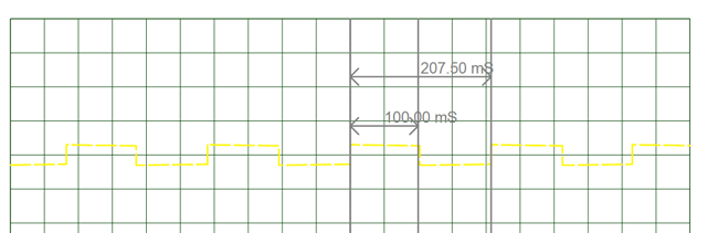
After downloading click on play button and you should see the graph as shown in the below image.
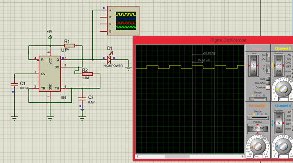
You can vary the resistor R2 and notice the Pulses getting varied based on the resistor value. This variation will affect how fast the LED turns on and off. The waveform is enlarged in the image below.
Working:
Once the connections are given simply power the circuit using a 9V battery. You should notice your LED flashing. If it looks stable, it means that it is flashing so fast that it is not visible to the naked eye. So gradually adjust the potentiometer to vary how fast it should flash. You can watch the video below for complete working of the project.
That is it we have a working of LED Strobe light setup. Hope you enjoyed the project and got it working, if not post your problems in the comment section and I will help you out.
Comments
What is the voltage rating and current rating of the LED. I cannot help without knowing this
10 watt and 12 volt LED will work,or you have another type of flasher circuit using 10watt and 12 volt LED ?
Hey Aswinth, can you help me guiding as if i want to run this circuit with 12 volts. What changes do i have to make. I cannot use 7805 as it will get hot.
I am looking for the same flashing but with 12 volts.
Please help.
Thanks
i have used all mention components above,but my LED is not Blinking,it is stable ? Please help me
0.01uF,0.1uF Capacitor these are the 2 capacitors are use ? right ?
Yes the value of capacitors are mentioned correctly.
If you are facing problem, replace the resistor with a potentiometer and try varing the resistane, it should help
This circuit can freeze moving fan?
What do you mean by freezing a moving fan? I cannot understand your application!!
Could you please explain to me where your constant in T= 1.1xCxR comes from?
I’m very curious about this kind of stuff
Its given in the datasheet. You need to analyze the internal circuit of a 555 timer of you wanna know how they arrived to this formula
I am interested in building a 430nm strobe that flashes at 250Hertz with a duration of 25 microsec/flash.
Do you think the above design would work?
250Hertz? I doubt if that frequency is supported by 555... Oh yes it will use the datasheet , just use the formula and change the values
I like the Curcuit In the Video ,But You do Not mention anything on what Moffset or Voltage Reg. You used .... Can you please tell me ?

if we want to put 10watt LED than what changes we have to made