

Solenoids are very commonly used actuators in many process automation systems. There are many types of solenoids. For instance, there are solenoid valves which can be used to open or close water or gas pipelines, and there are solenoid plungers which are used to produce linear motion. One very common application of a solenoid that most of us would have come across is the ding-dong doorbell. The doorbell has a plunger-type solenoid coil inside it, which, when energised by an AC power source, will move a small rod up and down. This rod will hit the metal plates placed on either side of the solenoid to produce the soothing ding-dong sound.
Although there are many types of solenoid mechanisms available, the most basic thing remains the same. That is, it has a coil wound over a metal (conductive) material. When the coil is energised, this conductive material is subjected to some mechanical movement, which is then reversed through a spring or other mechanism when de-energised. Since the solenoid involves a coil, it often consumes a large amount of current, making it mandatory to have some type of solenoid driver module to operate it. In this comprehensive tutorial, we will learn how to build a solenoid driver circuit to control a solenoid valve with a detailed circuit diagram and working explanation.
Table of Contents
- Components and Materials Required
- Quick Driver Circuit Selection Guide
- What is a Solenoid and how does it work?
- Current Requirements and Driver Necessity
- Circuit Diagram and Design Analysis
- Solenoid Valve Wiring Schematic Explanation
- └ MOSFET Selection Criteria
- └ Supporting Circuit Components
- Working and Operation
- └ Circuit Operation Sequence
- └ Testing and Demonstration
- Applications and Circuit Variations
- Troubleshooting and Safety Considerations
- Frequently Asked Questions
- Related Projects
Solenoid Driver Circuit: Components and Materials Required
To build an effective solenoid driver board, you'll need the following electronic components:
- Solenoid Valve
- 12V Adapter
- 7805 Regulator IC
- IRF540N MOSFET
- Diode IN4007
- 0.1uf Capacious
- 1k and 10k Resistors
- Connecting wires
- Breadboard
Quick Driver Circuit Selection Guide
Current Range | Recommended MOSFET | Gate Drive Voltage | Flyback Diode Rating | Heat Sink Required | Additional Protection |
|---|---|---|---|---|---|
< 0.5A | IRLZ44N, 2N7000 | 3.3V - 5V | 1N4148, 1A | No | Current limiting resistor |
0.5A - 2A | IRF540N, IRLB8721 | 5V | 1N4007, 1A | Optional | Flyback diode essential |
2A - 5A | IRF3205, IRLB3034 | 10V - 12V | UF4007, 1A Fast | Yes | Current sensing + Thermal protection |
> 5A | IRF1324, IRFB7546 | 12V | MBR360, 3A Schottky | Large heat sink | Current limiting + Over-temperature shutdown |
What is a Solenoid and how does it work?
A solenoid is a device that converts electrical energy into mechanical energy. It has a coil wound over a conductive material; this setup acts as an electromagnet. The advantage of an electromagnet over a natural magnet is that it can be turned on or off when required by energising the coil. Thus, when the coil is energised, according to Faraday's law, the current-carrying conductor has a magnetic field around it. Since the conductor is a coil, the magnetic field is strong enough to magnetise the material and create a linear motion.
Solenoid Current Requirements and Driver Necessity
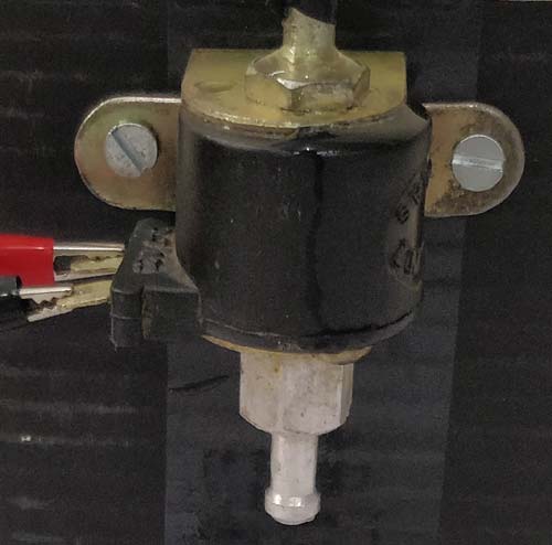
During this process, the coil draws a large amount of current and also produces a hysteresis problem; hence, it is not possible to drive a Solenoid coil directly through a logic circuit. Here we are using a 12V solenoid valve, which is commonly used in controlling the flow of liquids. The solenoid draws a continuous current of 700mA when energised and a peak of nearly 1.2A, so we have to consider these things while designing the driver circuit for this particular Solenoid valve.
Solenoid Circuit Diagram and Design Analysis
The complete solenoid circuit diagram for our driver circuit is shown below. We will understand why it is designed so, once after take a look at the complete circuit. The complete design of the solenoid driver board includes vital pieces of electronics to perform efficient and safe solenoid control, such as MOSFET switching, voltage regulation, and flyback protection.

Solenoid Valve Wiring Schematic Explanation
The solenoid valve wiring schematic provides an uncomplicated and efficient method for switching. A solenoid can be activated by applying a 12V signal across its connections and deactivated by removing the voltage signal. To control the switching control with digital logic, we use a MOSFET as the most important control element (or potential switch) in this driver circuit.
MOSFET Selection Criteria for Solenoid Driver Applications
As you can see, the circuit is very simple and easy to build, hence we can test this using a small breadboard connection. A solenoid can simply be turned on by powering 12V across its terminals and turned off by powering it off. To control this turn-on and off process using a digital circuit, we need a switching device like the MOSFET, and thus it is an important component in this circuit. The following are the parameters that you have to check while selecting the MOSFET.
Gate Source Threshold Voltage VGS(th): This is the voltage that has to be supplied to the MOSFET to turn it ON. Here, the threshold voltage value is 4V, and we are supplying a voltage of 5V, which is more than enough to turn on the MOSFET completely
Continuous Drain Current: The continuous drain current is the maximum current that can be allowed to flow through a circuit. Here, our solenoid consumes a maximum peak current of 1.2A, and the rating of our MOSFET is 10A at 5V Vgs. So we are more than safe with the current rating of the MOSFET. It is always recommended to have some upper marginal difference between the actual value and the rated value of current.
Drain-Source On-State Resistance: When the MOSFET is fully turned on it has some resistance between the Drain and Source pins; this resistance is called on-state resistance. The value of this should be as low as possible; there will be a huge voltage drop (Ohm's law) across the pins, resulting in sufficient voltage for the Solenoid to turn on. The value of on-state resistance here is only 0.077Ω.
Supporting Circuit Components
You can look at the datasheet of your MOSFET if you are designing the circuit for some other Solenoid application. A 7805 Linear Regulator IC is used to convert the 12V input supply to 5V. This voltage is then given to the Gate pin of the MOSFET when the switch is pressed through a 1K current-limiting resistor. When the switch is not pressed, the gate pin is pulled down to ground through a 10k Resistor. This keeps the MOSFET turned off when the switch is not pressed. Finally, a diode is added in the anti-parallel direction to prevent the solenoid coil from discharging into the power circuit.
Solenoid Driver Circuit Working and Operation
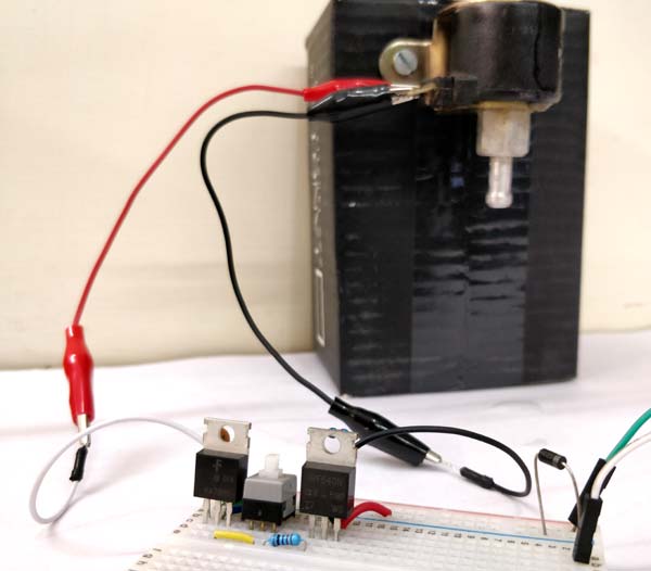
Now that we have understood how the Solenoid Driver circuit works, let's test the circuit by building it on a breadboard. I have used a 12V adapter for the power supply, and my hardware setup looks something like this when completed. Understanding the working principle of our solenoid driver module is essential for successful implementation.
Circuit Operation Sequence
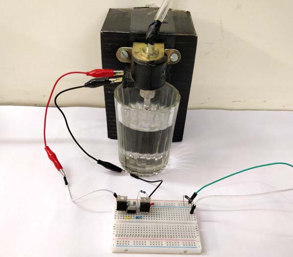
When the switch is pressed, the +5V supply is provided to the MOSFET, and it turns on the Solenoid. When the switch is pressed again, it disconnects the +5V supply to the MOSFET, and the solenoid goes back to the off state. The turning on and off of the solenoid can be noticed by the clicking sound made by it makes, but to make it a bit more interesting, I have connected the solenoid valve to a water pipe. By default, when the solenoid is off, the valve is closed, and hence no water comes out through the other end. Then when the solenoid is turned on, the valve opens and water flows out. The work can be visualised in the video below.
Practical Testing and Demonstration
One can verify the solenoid is operating because one can hear the noticeable clicking sound when energising it and when de-energising it. To demonstrate a more obvious effect, we connected the solenoid valve to a water pipe system. The valve defaults to being in the OFF state. At the closed valve position, water shall not be granted passage through the system. The circuit, once triggered, opens the valve to allow water to flow through the system, thus proving the performance of the circuit.
Applications and Circuit Variations
The solenoid driver circuit could be tailored to various applications such as irrigation, pneumatic controls, automotive, industrial automation, etc. When the solenoid driver circuit is integrated with a microcontroller, the only difference is essentially using a digital output pin in place of the manual switch, keeping the current handling and protection scheme of this circuit further intact.
Troubleshooting and Safety Considerations
Make sure that the solenoid current ratings are in agreement with your driver specifications at all times. Make sure that the voltage regulator is capable of dissipating heat properly, considering your solenoid will probably be on continuously. Make sure to include the flyback diode, as inductive kickback could damage any semiconductors. Lastly, consider positioning thermal management components and EMI suppression components if you will be frequently switching the solenoid.
You now have all the information you need to construct retrievable solenoid driver circuits for various applications in automation and control. The simplicity of the circuit, combined with a variety of hard-nosed protection features, makes the circuit equally valuable in an academic environment and for practical use.
Hope you understood the project and enjoyed building it. If you have faced any problem, then feel free to post it in the comment section or use the forum for technical help.
Frequently Asked Questions about Solenoid Driver Module
⇥ 1. What is a solenoid driver circuit?
A solenoid driver circuit is an electronic circuit that supplies enough current and voltage to safely control solenoids. The driver circuit usually contains switch devices such as MOSFETs or transistors, which can switch high currents that solenoids draw. The driver circuit also provides isolation from the solenoid, so a low-power control circuit won’t get damaged.
⇥ 2. Why can't I just connect the solenoid to my microcontroller?
Solenoids need a significant amount of current (typically 500mA-2A) that is more than the microcontroller's output ratings (generally 20-40mA). You can damage your microcontroller by over-drawing current. Solenoids also create back-EMF voltage spikes that the femto-second response characteristics of semiconductor components like transistors cannot save you from - they can be damaged if not properly protected.
⇥ 3. What type of MOSFET would I want to use for a 12V solenoid driver?
A MOSFET should have drain current ratings of 2-3 times that of the solenoid peak current, low RDS(on) of < 0.1Ω, and VGS(th) of < 4V. Some commonly used MOSFETs for a standard 12V solenoid are IRF540N, IRLZ44N, and the IRF3205.
⇥ 4. Why should I use a flyback diode for solenoid circuits?
Each flyback diode is used to protect the circuit from sudden surges of back-EMF (electromotive force) voltage spikes produced when the solenoid is turned off.. Without these voltage spikes, when the solenoid coil releases its energy, it could generate excessive voltage spikes that could destroy not only MOSFETs but also many other parts of the circuit.
⇥ 5. How does one calculate the current requirement for his/her solenoid?
Look into the solenoid datasheet for hold current (continuous operation) and pull-in current (initial activation). Otherwise, see if you can measure it with a multimeter. Typically, 12V solenoids should draw 200mA-1.5A. Your driver circuit should ideally be designed for 150% of the maximum current rating.
Related Actuator & Motor Control Projects
Expand your practical knowledge of controlling electromechanical devices with these hands-on projects. From driving solenoids and relays to testing servo motors and managing DC motor speed and direction, these circuits provide a strong foundation in actuator interfacing and precise motion control using both analog and microcontroller-based techniques.

Servo Tester Circuit using IC 555
Servo motors are commonly used in many embedded system applications. This tutorial explains how to test a servo motor using a simple 555 timer based servo tester circuit.

Arduino DC Motor Speed and Direction Control using Relays and MOSFET
In this project we control direction and speed of a 24v high current motor using Arduino and two relays. No power switches are needed for this circuit, just two push buttons and in Potentiometer to control the direction and speed of DC Motor.

4-Channel Relay Driver Circuit and PCB Design
In this project we will make a 4-Channel Relay Driver Circuit for relay based applications. Here we designed an isolated PCB for 4 relays so we can operate 4 AC appliances at a time.
Comments
The mosfet will not turn off if the gate pin is not pulled down to ground
The parts list states 2 resistors, one as 1k the other as 10k
The diagrahm shows both as 10k
The write up says the 10k is to ground the mosfet
So I assume the other is actually 1k and goes to the regulator?
Thanks for doing this for other than Arduino as I am using this with a physical switch.
How hot does the 7805 get? Will it require a heat sink?
Thanks!!!!
The schematic shows the gate driven from the middle of a voltage divider that divides the 5 volts from the regulator by two, resulting in 2.5V.
But the text says:
"Here the threshold voltage value is 4V and we are supplying a voltage of 5V which is more than enough to turn on the MOSFET completely."
If we assume that R1 was supposed to be 1K, the we're feeding the gate 10k/11k * 5V which is 4.5V. That's enough to turn on the MOSFET, but it's not 5V.

What's the purpose of the +5 V regulator? It's an added 2 parts that might not be necessary.
The voltage applied to the gate will be about 2.5V with the resistive divider you've set up, which is a bit short of 4V, but 4V is the max Tgs.
It might be a better example to do that circuit with the intention of driving it from an Arduino or Pi, which many would be using I expect.
Chris