

If you are working with any Audio related project, the least concerned component is the Speaker but the speaker is an essential part of any audio related circuit. A good speaker can override the noises and can provide a smooth output whereas a bad speaker can destroy your all efforts even the rest of the circuit is exceptionally good.
So, it is important to select proper Speaker as it is the one which is producing final output for end audiences. But, as we all know, while making a circuit, all the components are not always readily available and sometimes we could not determine what will be the output if we select a specific speaker or sometimes we have a speaker but do not have the Enclosure. So this is a large concern as the speaker output can be completely different in different types of acoustic environments.
So, How to determine what will be the speaker response in a different situation? Or, what will be the circuit construction? Well, this article will cover this topic. We will understand how the speaker works and will construct an RLC equivalent model of Speaker. This circuit will also serve as good tool to simulate speaker in some specific applications.
Construction of a Speaker
Speaker act as an Energy converter, which converts Electrical energy into Mechanical Energy. A speaker has two level of constructions, one is Mechanical and another one is the Electrical.
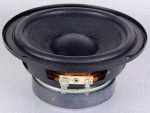
In the below image we can see the cross-section of a Loudspeaker.
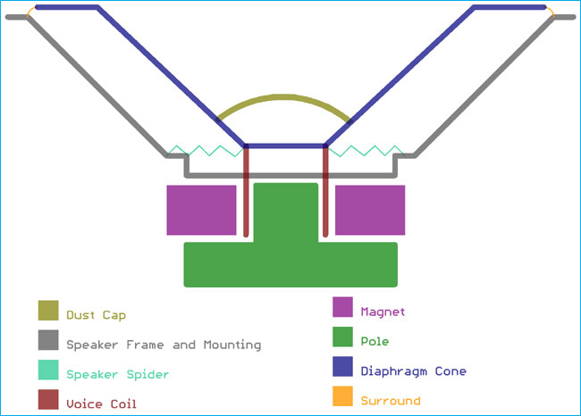
We can see a Speaker Frame or Mount which is holding the components at inside and outside. The components are Dust cap, Voice coil, Diaphragm Cone, Speaker Spider, Pole, and Magnet.
The Diaphragm is the end thing which vibrates and pushes the vibration to the air and thus changing the air pressure. Because of its cone shape, the Diaphragm referred as Diaphragm Cone.
The spider is an important component which is responsible for the proper movement of the Speaker diaphragm. It ensures that when the cone will vibrate, it will not touch the Speaker Frame.
Also, the surround, which is rubber or foam-like material, provides the additional support to the Cone. The Diaphragm cone is attached with an Electromagnetic coil. This coil can freely move in up-down position inside the pole and Permanent Magnet.
This coil is the Electrical part of the speaker. When we provide sinusoidal wave to the speaker the voice coil changes the magnetic polarity and moves up and down which in result creates vibrations in the cone. The vibration further transferred to the air by either pulling or pushing te air and making changes in air pressure, thus creating sound.
Modeling a Speaker into the Electrical circuit
Speaker is the main component for all the Audio Amplifier circuits, mechanically, a speaker work with lots of physical components. If we make a list then the consideration points will be-
- Suspension Compliance – This is the property of a material in which the material goes under elastic deformation or experience the change in volume when it is subjected to an applied force.
- Suspension Resistance – It is the load, the cone is facing while moving from the suspension. It is also known as Mechanical Damping.
- Moving Mass - It is the total mass of the Coil, Cone etc.
- Load of the air which is pushing through the driver.
These above four points are from Mechanical factors of the speaker. There are two more factors are present electrically,
- Coil Inductance.
- Coil Resistance.
So by considering all the points, we could make a physical model of the speaker using few electronics or electrical components. Those above 6 points can be modeled using three basic passive components: Resistors, Inductors, and Capacitors which are denoted as RLC circuit.
A basic equivalent circuit of the speaker can be made by only using two components: Resistor and Inductor. The circuit will look like this-
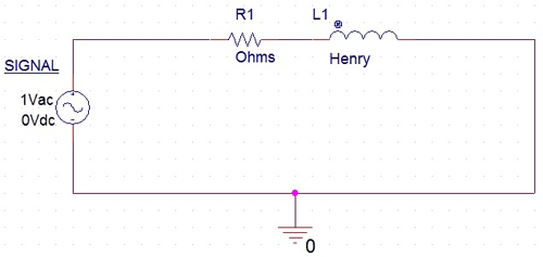
In the above image, only a single Resistor R1 and single Inductor L1 is connected with an AC signal source. This resistor R1 represents the voice coil resistance and the Inductor L1 provides the Voice coil Inductance. This is the simplest model used in Speaker simulation but certainly, it has limitation, because it is only an electrical model and there is no scope to determine the speaker ability and how it will react in actual physical scenario where mechanical parts are involved.
Speaker Equivalent RLC Circuit
So we have seen a basic model of speaker but to make it work properly, we need to add mechanical parts with actual physical components in that speaker equivalent model. Let’s see how we can do it. But before understanding this, let’s analyze what components are needed and what is the purpose of them.
For Suspension Compliance, a inductor can be used, because the Suspension Compliance has a direct connection with the certain change in current flow through the Voice coil.
Next parameter is the Suspension Resistance. As it is a type of load which is created by the suspension, a resistor can be selected for this purpose.
We can select a capacitor for the moving mass, which includes coils, the mass of the cone. And further we can select a capacitor again for the air load which also increases the mass of the cone; it is also an important parameter for creating the speaker equivalent model.
So, we have selected one inductor for the Suspension Compliance, one resistor for suspension resistance, and two capacitors for our Air load, and moving mass.
Now, the next important thing is how to connect all these to make an electrical equivalent model of speaker. The resistance (R1) and inductor (L1) are in series connection which is primary and which is variable using the parallel mechanical factors. So, we will connect those components in parallel with the R1 and L1.
The Final circuit will be like this-

We have added components in parallel connection with the R1 and L1. C1 and C2 will denote the moving mass and air load respectively, L2 provide Suspension Compliance and R2 will be the suspension resistance.
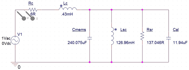
So, the final equivalent Circuit of the speaker using RLC is shown below. This image is showing an exact equivalent model of the speaker using Resistor, Inductor, and capacitor.
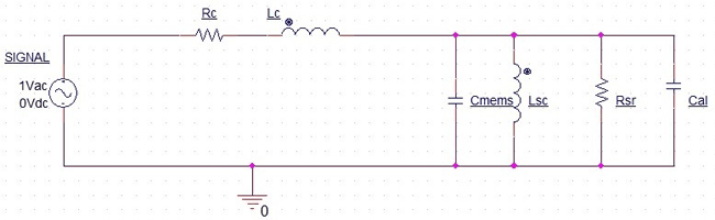
Where, Rc – Coil Resistance, Lc – Coil Inductance, Cmems – Moving mass capacitance, Lsc – Inductance of Suspension Compliance, Rsr – Suspension Resistance and Cal – Capacitance of the air load.
Thiele/Small Parameters in Speaker Design
Now we got the equivalent model, but how to calculate the value of the components. For this, we need Thiele small Parameters of the Loud Speaker.
The small parameters are derived from the input impedance of the speaker when the input impedance is the same as the resonant frequency and the mechanical behavior of the speaker is effectively Linear.
Thiele Parameters will provide the following things-
|
Parameters |
Description |
Unit |
|
Qts |
Total Q factor |
Unitless |
|
Qms |
Mechanical Q factor |
Unitless |
|
Qes |
Electrical Q factor |
Unitless |
|
Fs |
Resonant Frequency |
Hz |
|
Rms |
The resistance of the Suspension |
N. s/m |
|
Mmd |
Total moving mass |
Kg |
|
Sd |
Effective driver area |
Sq.m |
|
Vas |
Equivalent acoustic volume |
Cu.m |
|
Xmax |
Linear travel of voice coil |
M |
|
FR |
Frequency Response |
Hz or kHz |
|
Vd |
Driver unit volume displacement |
Cu.m |
|
Revc |
The resistance of the voice coil |
Ohms |
|
Levc |
Coil Inductance |
Henry or Mili Henry |
|
Bl |
Force Factor |
Tesla / metres |
|
Cms |
Compliance of Driver Suspension |
Meters per Newton |
From these parameters, we can create an equivalent model using simple formulas.
Value of Rc and Lc can be directly selected from coil resistance and inductance. For other parameters, we can use the following formulas –
Cmens = Mmd / Bl2
Lsc = Cms * Bl2
Rsr = Bl2 / Rms
If the Rms not given, then we can determine it from the following equation-
Rms = (2*π*fs*Mmd) / Qms
Cal = (8*p*Ad3) / (3*Bl2)
[Where Ad is effective radius of cone = Square root of (Sd / 3.14) and p is the density of air at 25 degree Celsius = 1.184 kg/m3]
Building RLC Equivalent Speaker Circuit with Real Data
As we learned how to determine the equivalent values for the components, let’s work with some real data and simulate speaker.
We selected 12S330 speaker from BMS Speakers. Here is the link for the same.
http://www.bmsspeakers.com/index.php?id=12s330_thiele-small
For the speaker the Thiele Parameters are
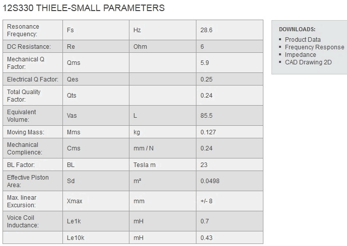
From this Thiele Parameters, we will calculate the equivalent values,
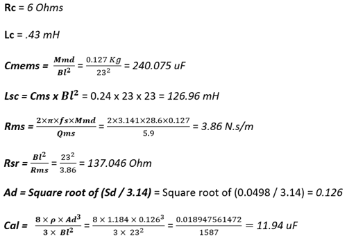
So, we calculated the values of each component to be used for 12S330 equivalent model. Let’s make the model in Pspice.
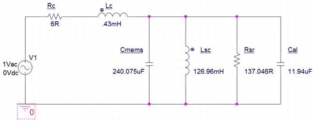
We provided the values to each component and also renamed the signal source to V1. We created a simulation profile-
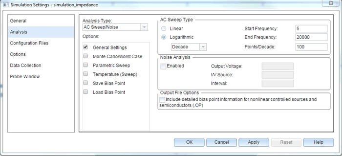
We configured the DC sweep to get the large frequency analysis from 5 Hz to 20000 Hz at 100 points per Decade in Logarithmic scale.
Next, we connected the probe across our equivalent speaker model input-
We added Voltage and Current trace across Rc, the resistance of the voice coil. We will check the impedance across this resistor. To do this, as we know, V = IR and if we divide the V+ of AC source with the current flowing through the resistor Rc, we will get the impedance.
So, we added a trace with V(V1:+)/I(Rc) formula.
And finally, we get the Impedance plot of our equivalent speaker model of 12S330.
We can see the Impedance plot and how the Speaker impedance changes depending on the frequency-
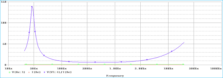
We can change the values as per our need and we can now use this model to replicate actual 12S330 Speaker.

Thank you very much. I ported this model to LTSpice and worked well.
You are in mention as original author on github.