Peak Detector Circuit is used to find the peak amplitude in a rapidly changing waveform. Peak detectors are generally used in the sound measuring applications to find the maximum level of sound in a particular area or place, that helps in determining the maximum loudness level in that place. So, like this there are number of applications where a Peak Detector Circuit is used. For a Basic Peak Detector Circuit, we don’t even need any complex electronics components. A Simple Peak Detector Circuit can be built by using a diode and a capacitor.
Basic Peak Detector Circuit
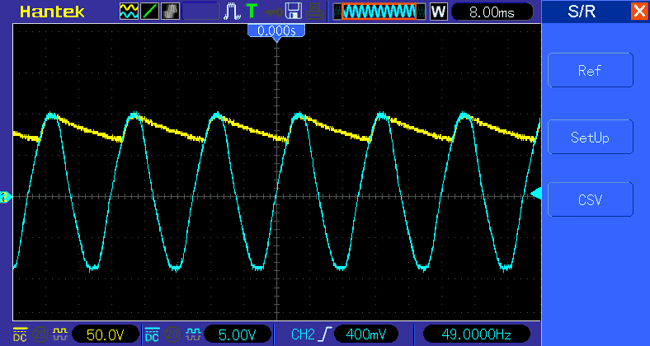
A basic peak detector circuit is a connection of a diode and a capacitor in series. In our circuit, we are giving a sine wave input from a 220v to 6v step-down transformer. The diode is placed in forward biased condition and for output, the oscilloscope probe is connected between the diode and capacitor. Below is the schematics for a Basic Peak Detector Circuit.


In the positive half cycle of the signal, the diode will be forward biased and allows the current to pass through it. At the same time, the capacitor starts charging to the peak value of the input signal until the diode remains forward biased.
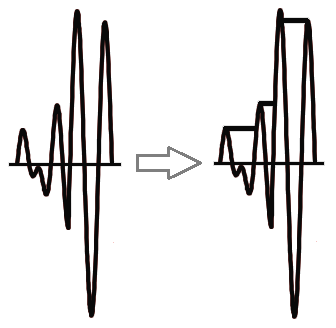
Now, in the negative half cycle of the signal, the diode gets reverse biased and at that time the capacitor holds the peak value of the previous half cycle. Hence, this is called as Peak Detector and the output waveform will look like the image given below,
Practically the output is taken across some load connected to the circuit. So, when the input signal is decreasing the capacitor starts discharging through the load RL. To hold the charge and slow down the discharging of capacitor choose the load RL of very high value.
The output of the circuit will be defined as
VOUT = VIN - VD
Where VIN is the input signal voltage and VD is the voltage drop across the diode. Here, in the output waveform, you can the see the peak is shifted down because of the voltage drop acrosss the diode in the circuit. So, this voltage drop at diode reduces the efficiency of the circuit, and to improve the design next we will use Op-amp.
For detecting the negative peak of the input signal connect the diode in the reverse condition.
Op-amp based Peak Detector Circuit
Op-amp based peak detector circuit is the modification of basic peak detector circuit, used to remove the voltage drop across the diode. Whenever the applied input voltage signal is greater than the threshold voltage of the diode, the diode will get forward biased and acts as a closed switch. Here, the diode is connected in the feedback and hence the circuit works as a buffer circuit. So, whatever input is applied to the positive terminal of the op-amp will be received at the output terminal.
Material Required
- Oscilloscope
- LM741- Op-amp IC
- Diode - 1N4007
- Resistor (10k) - 3nos.
- Capacitor (4.7uf) - 1nos.
- Breadboard
- Jumping Wires
Circuit Diagram


Working of the Op-amp based Peak Detector Circuit
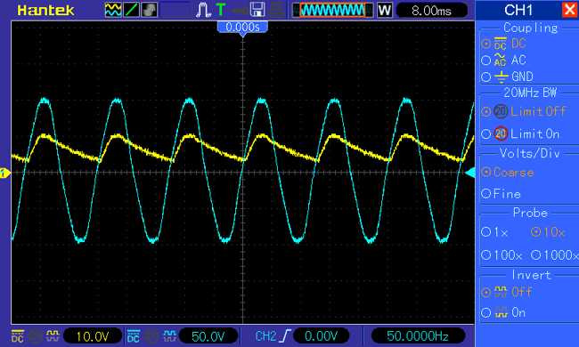
In the first positive half cycle, the op-amp output is HIGH, so the diode is forward biased. At the same time, the capacitor charges to the highest peak value of the input signal. Here, the circuit is working as a voltage follower buffer circuit.
In the first negative half cycle, the op-amp output is LOW so the diode will be reversed biased. Therefore, until the diode again gets forward biased the capacitor holds the peak value of the input signal. In this reverse biased condition of the diode, the op-amp is in open loop condition and goes into saturation, so the capacitor starts discharging into the RL. That’s why you will see the decreasing slope in the negative cycle of the signal.
The output waveform of the op-amp based peak detector circuit is given below: