
In this project, we will make an 8-channel Motor Driver Module Circuit for motors based applications. In this circuit, we have designed a PCB for driving DC or stepper motors. By using this motor driver board we can operate 8 DC motors or four 4-wire stepper motors at a time. In this board, we have used few three pin screw terminal blocks and burgsticks, connected from the same pins, so that you can either use burgsticks or wires for connecting motors. Here we have used four L293D Motor Driver ICs for driving motors.
Components Required:
- Motor Driver IC L293D -4
- 104 capacitors -4
- 2 Pin Screw terminal Block -8
- 3 Pin Terminal Block -1
- SMD LED -1
- PCB (ordered from JLCPCB) -1
- Resistor 1k -1
- Burg sticks male
- Power supply
- Microcontroller or Arduino
- Connecting wire
Motor Driver Circuit Explanation:
In this Motor Driver Circuit, we have used four L293D motor driver ICs for driving motors. This board is capable to drive 8 DC motor or 4 stepper motors at a time. User can use this board for to build their DC or stepper motor based projects like a Robotic Arm, Line Follower, land robbers, maze followers and many other projects. This board can be controlled by using a microcontroller. This board has screw terminal and burgsticks for connect motors. Here we have used burgsticks for connecting the controlling pins to microcontrollers or Arduino. This board has jumper pins to select either hardware controlled mode or software controlled mode, means user may control these pin either by programming or by putting a jumper wire in hardware motor driver board using jumper connector. This board has 12v, 5v supply option for power. There are some general purpose holes also available for placing any required components.

We have designed this board to be understood easily. User can understand the connections by reading pins name (mentioned over PCB board).
Working and Demonstration:
For demonstration, we have used an Arduino board for controlling 2 DC motors and 1 stepper motor. We have connected stepper motor at 8,9,10 and 11th pins of L293D (In21, In22, In23, and In24 motor driver pins) and Enable pin (Jumper) is set in hardware controlled mode by putting HIGH by using jumper connector.
DC motors are connected at 3, 4, 5 and 6th pin of L293D (IN11, IN12, IN13, IN14 motor driver board pin) and Enable pin (Jumper) is set in software controlled mode, connected at 2, 3 pins (1EN12 and 1EN34 Motor driver Pins). 5v power supply is used for powering circuit and motors.

Below is the Arduino Code which we have used to demonstrate this Motor Driver Module:
#include <Stepper.h>

const int stepsPerRevolution = 200;
Stepper myStepper(stepsPerRevolution, 10, 9, 8, 11);

#define _1EN12 2
#define _1EN34 3
#define IN11 4
#define IN12 5
#define IN13 6
#define IN14 7

void setup()
{
  pinMode(_1EN12, OUTPUT);
  pinMode(_1EN34, OUTPUT);
  pinMode(IN11, OUTPUT);
  pinMode(IN12, OUTPUT);
  pinMode(IN13, OUTPUT);
  pinMode(IN14, OUTPUT);

  digitalWrite(_1EN12, LOW);
  digitalWrite(_1EN34, LOW);
}

void loop()
{

 stepperMotor();
 delay(5000);

  forwardFirstMotor();
  startFirstMotor();
  delay(5000);

  stopFirstMotor();
  delay(2000);

  forwardSecondMotor();
  startSecondMotor();
  delay(5000);

  stopSecondMotor();
  delay(2000);

  startFirstMotor();
  startSecondMotor();
  delay(5000);

  stopFirstMotor();
  stopSecondMotor();
  delay(2000);

  reverseFirstMotor();
  startFirstMotor();
  delay(5000);

  stopFirstMotor();
  delay(2000);

  reverseSecondMotor();
  startSecondMotor();
  delay(5000);

  stopSecondMotor();
  delay(2000);

  startFirstMotor();
  startSecondMotor();
  delay(5000);

  stopFirstMotor();
  stopSecondMotor();
  delay(2000);

  forwardFirstMotor();
  startFirstMotor();
  startSecondMotor();
  delay(5000);

  stopFirstMotor();
  stopSecondMotor();
  delay(2000);

  reverseFirstMotor();
  forwardSecondMotor();
  startFirstMotor();
  startSecondMotor();
  delay(5000);

  stopFirstMotor();
  stopSecondMotor();
  delay(2000);
}

void forwardFirstMotor()
{
  digitalWrite(IN11, HIGH);
  digitalWrite(IN12, LOW);
}

void forwardSecondMotor()
{
  digitalWrite(IN13, HIGH);
  digitalWrite(IN14, LOW);
}

void reverseFirstMotor()
{
  digitalWrite(IN11, LOW);
  digitalWrite(IN12, HIGH);
}

void reverseSecondMotor()
{
  digitalWrite(IN13, LOW);
  digitalWrite(IN14, HIGH);
}

void stopFirstMotor()
{
  digitalWrite(_1EN12, LOW);
}

void stopSecondMotor()
{
  digitalWrite(_1EN34, LOW);
}

void startFirstMotor()
{
  digitalWrite(_1EN12, HIGH);
}

void startSecondMotor()
{
  digitalWrite(_1EN34, HIGH);
}

void stepperMotor()
{
  for(int i=0;i<2000;i++)
  {
    myStepper.step(1);
    delay(10);
  }
}
Also check the Video at the end of this article.
Circuit and PCB Design using EasyEDA:
To design this Motor Driver Circuit, we have chosen the online EDA tool called EasyEDA. We have previously used EasyEDA many times and found it very convenient to use compared to other PCB fabricators. Check here our all the PCB projects. After designing the PCB, we can order the PCB samples by their low cost PCB fabrication services. They also offer component sourcing service where they have a large stock of electronic components and users can order their required components along with the PCB order.
While designing your circuits and PCBs, you can also make your circuit and PCB designs public so that other users can copy or edit them and can take benefit from there, we have also made our whole Circuit and PCB layouts public for this Motor Driver Module, check the below link:
https://easyeda.com/circuitdigest/Motor_Driver-10abfdf903214b24a6ae83eb182ae2e6
You can view any Layer (Top, Bottom, Topsilk, bottomsilk etc) of the PCB by selecting the layer form the ‘Layers’ Window.
You can also view the PCB, how it will look after fabrication using the Photo View button in EasyEDA:

Calculating and Ordering Samples online:
After completing the design of PCB, you can order the PCB through jlcpcb.com. To order the PCB from JLCPCB, you need Gerber File, which you can download from the EasyEDA PCB order page. To download Gerber files of your PCB just click the Fabrication Output button in EasyEDA.
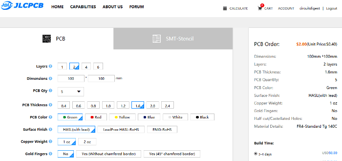
Then go to jlcpcb.com and click on Quote Now or Buy Now button, then you can select the number of PCBs you want to order, how many copper layers you need, the PCB thickness, copper weight, and even the PCB color, like the snapshot shown below:
After you have selected all of the options, click “Save to Cart” and then you will be taken to the page where you can upload your Gerber File which we have downloaded from EasyEDA. Upload your Gerber file and click “Save to Cart”. And finally click on Checkout Securely to complete your order, then you will get your PCBs a few days later. They are fabricating the PCB at very low rate which $2.


After few days of ordering PCB’s I got the PCB samples

Soldering: after getting these pieces I have mounted all the required components over the PCB connected it with Arduino for demonstration.

Also check the Video below.
