You have seen many LED torches in the market, mostly use white LEDs as they provide good brightness and light. Today we are making the low cost and highly efficient Simple LED torch light Circuit which allows your battery to live longer, for this we are using a 4049 hex inverter buffer IC. By the help of this IC, we are making a voltage multiplier circuit which doubles the input voltage value and we are able to glow three white LEDs with the only 5v of input supply.
Material Required
- CD4049 IC
- LEDs - 3 (white color)
- Supply 5v
- Resistor (6.7k ohms)
- Capacitor 0.1uf and 220uf (2nos)
- Diode 1N4007 -2
- Connecting wires
Circuit Diagram

Need of IC 4049 for LED torch Circuit:
As we know it is impossible to glow three white LEDs in series with full brightness using 5v/20mA directly, if we connect the LEDs in parallel the value of current will increase and the battery will drain fastly. So we need to increase the voltage by making a voltage multiplier circuit, for this we are using a 4049 hex inverter buffer IC. In this IC there are six NOT gates, as per the circuit diagram two are used to make an oscillator circuit whose output is attached with the 4 NOT gate connected in parallel as a buffer.
Here we have built a voltage Doubler circuit by using two diodes, two electrolytic capacitors and 4 not gates inside IC 4049. This circuit can double only alternating voltage so we have created a oscillator circuit using resistor R1, capacitor C1 and two NOT Gates of IC CD4049. In this LED torch Circuit, we have powered the circuit by 5v DC so we will get approx. 10v at the output across capacitor C3. This doubled output voltage is enough to light up the three white LEDs in series.
4049 Inverting Hex Buffer IC
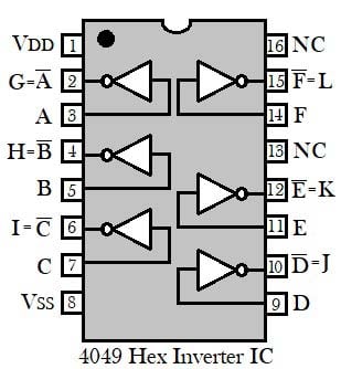
CD4049 IC just a simple IC, contains six NOT gate inside it with a high rating input supply voltage of 5v to 15v, and maximum current rating at 18v is 1mA. The IC is planned or made to use as CMOS to DTL/TTL converters and also able to drive two TTL (Transistor-Transistor Logic) or DTL (Diode-Transistor Logic) loads. Operating temperature of the IC is -40°C to 80°C. We can use the IC to make square wave oscillator generator or Pulse generator circuit. Also used for converting logic levels of up to 15 v to standard TTL levels which are 0 to 0.8v (low voltage level) and 2v to 5v (high voltage level).
Pin Diagram

Pin Configuration
|
Pin Name |
Pin Number |
I/O |
Description |
|
A |
3 |
I |
Input 1 |
|
B |
5 |
I |
Input 2 |
|
C |
7 |
I |
Input 3 |
|
D |
9 |
I |
Input 4 |
|
E |
11 |
I |
Input 5 |
|
F |
14 |
I |
Input 6 |
|
G |
2 |
O |
Inverting output 1 for input 1 |
|
H |
4 |
O |
Inverting output 2 for input 2 |
|
I |
6 |
O |
Inverting output 3 for input 3 |
|
J |
10 |
O |
Inverting output 4 for input 4 |
|
K |
12 |
O |
Inverting output 5 for input 5 |
|
L |
15 |
O |
Inverting output 6 for input 6 |
|
VDD |
1 |
- |
Positive supply for IC |
|
VSS |
8 |
- |
Negative supply for IC |
|
NC |
13,16 |
- |
Not connected |
Applications
- CMOS to DTL/TTL Hex Converters
- High sink current for driving two TTL loads
- Convert logic level from high to low
Working of Simple LED Torch Light Circuit
The supply voltage is given to the circuit is 5v DC. In the circuit, the resistor R1 and capacitor C1 are arranged with two NOT gate to make an oscillator circuit. The remaining 4 NOT gates connected in parallel to make a buffer and double the input voltage.

As we turn on the supply capacitor C2 starts charging, through the buffer created by 4 not gates, till the peak of the input voltage (5v). And now C2 acts as a second power source of 5v, so with D1 and D2 forward biased, capacitor C3 charges with the combined voltages of the power supply and capacitor C2. So with a combined voltage of both, capacitor C3 charges up to nearly 10v. This output voltage is enough to glow three white LEDs and we have a Bright LED Torch.


