

In this tutorial, we will show you how to connect a Laser diode in an electronic circuit. In comparison to LED’s light, Laser light is highly concentrated, it’s have smaller and narrower viewing angle. For connecting a laser diode in an electronic circuit we need a Laser diode driver circuit.
Required Components
- Laser Diode module (650nm, 5mw)
- LM317 Voltage Regulator IC
- 1µF electrolytic capacitor
- 0.1µF ceramic capacitor
- 300Ω Resistor
- 10k potentiometer
- Battery 9v
Circuit Diagram

Laser Diode Driver Circuit
A Laser Diode driver circuit is a circuit which is used to limit the current and then supplies to the Laser Diode, so it can work properly. If we directly connect it to the supply, due to more current it will damage. If current is low then it will not operate, because of not having sufficient power to start. So, a driver circuit is needed to provide a correct value of current by which Laser Diode comes into operating condition. A simple LED only need a resistor to limit the current but in Laser diode we need proper circuitry to limit and regulate the current. Generally LM317 is used for regulating Power in Laser Diode Driver Circuit.
Laser Diode (650nm, 5mw)
A Laser Diode is a device which emits light by the process of optical amplification depend on stimulated emission of electromagnetic radiation, in simple we can say it Laser light. The full form of Laser is “Light Amplification by Stimulated Emission of Radiation”. A laser light is different from other source of light as it release the light coherently, spatially and temporally. Laser light is monochromatic in nature, which means it’s just one light with same wavelength and energy, not a combination of colors of light.
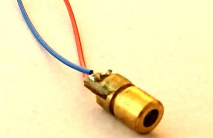
1. Construction of Laser Diode
Laser Diode is consists of two semi-conductors, sand-wiched together. On the top it have Gallium Arsenide whose property is too filled by an electron, as it’s having holes. The semiconductor which takes electrons are called as P-type semi-conductor. On the bottom part it have Gallium Arsenide & Selenium whose property is to fill a hole, as it is having an extra electron. The semi-conductors which give extra electron are called as N-type semi-conductor. This construction format creates a P-N junction in between of them, in which Laser light is produced.
2.Working of Laser Diode
As current through a semi-conductor passes, both negatively charge electrons and positively charged holes start flowing towards the P-N junction. When an electron and hole combines together, due to existence of hole in lower energy level than electron it lose some amount of energy to combine with an electron. That energy comes out in the form of a photon. For the trapping of that photon of light, top and bottom surface of the P-N junction is coated with mirrored material. Then this photon encouraged other holes and electrons to combine and release photon. This process will end up when whole P-N is filled with laser light and then it continuously emits laser light outside through it.
3. Applications
- Industrial applications: Engraving, cutting, scribing, drilling, welding, etc.
- Medical applications: to remove unwanted tissues, diagnostics of cancer cells using fluorescence, dental medication.
- Telecommunication
- Military application
- Data storage
LM317 Voltage Regulator IC
It’s an adjustable three-terminal voltage regulator IC, it can gives and output voltage of 1.25 v to 37v. Which we can vary according to the need by using two external resistors on adjustable PIN of LM317. These two resistors works as voltage divider circuit used to increase or decrease the output voltage. The LM317 IC helps in current limiting, thermal overload protection and safe operating area protection. If we disconnect the adjustable terminal still LM317 will helpful in Overload protection. It’s having a typical line and load regulation of 0.1%.
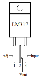
PIN NO. | PIN Name | PIN Description |
1 | Adjust | We can adjust the Vout through this pin, by connecting to resistor divider circuit. |
2 | Output | Output voltage pin (Vout) |
3 | Input | Input voltage pin (Vin) |
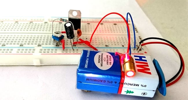
Working of Laser Diode Driver Circuit
As battery start giving supply, it first flow through the ceramic capacitor (0.1uf). This capacitor is used to filtering high-frequency noise from our DC source, and gives to input PIN3 of the LM317 voltage regulator IC. The potentiometer (10k) and resistor are used as the voltage limiting circuit connected with the adjustable PIN1. The output voltage is completely depends on the value of these resistor and potentiometer. Then the output voltage is taken out from the Output PIN2 and this voltage filter out from the second capacitor (1uf). This capacitor behaves as a power load balancer to filter the fluctuating signals. We can adjust the intensity of laser light by moving the potentiometer.

great work. was searching for this circuit