
We are very much familiar with our television sets, DVDs, MP3 players, music systems and many other device that are controlled by using IR Remote. There are many types of remote controls available for different devices but most of them work on around 38KHz Frequency signal. Sometimes we face a common problem related to IR TV or other device remote control that if it is working or not. We check multiple times to find if the remote is working or not. Here we are going to make an IR Remote tester circuit using TSOP1738 IR Receiver sensor circuit. This TSOP1738 sensor can sense 38Khz Frequency signal and can detect any IR signal.
Components Required
- TSOP1738
- LM7805 Voltage Regulator
- 1K resistor
- 150 ohm Resistor
- 1000uF capacitor
- Jumper wires
- Bread board
- 9 Volt Battery
- Battery Connector
- Buzzer
- LED
- TV Remote
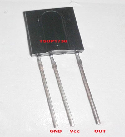
When TSOP1738 sensor gets IR pulses or signal its output pin goes LOW and become HIGH again when signal is lost. By default output pin remains in HIGH state. A TSOP1738 sensor is shown in the below image.
Circuit Diagram and Explanation

As shown in the above IR remote control tester circuit, we have connected a buzzer and a yellow LED for indication. LM7805 Voltage regulator is also added in to the circuit for providing 5 volt voltage supply to the circuit, and a 9 volt battery is used for powering the circuit. Pin number 1 of LM7805 is connected to battery’s Positive terminal and pin second is connected to ground terminal of battery. Pin 2 of TSOP1738 is directly connected with pin number 3 of LM7805 and first number is connected to ground. Buzzer is connected to pin number three of TSOP1738 trough a 1K resistance and yellow LED’s negative terminal is connected with the same terminal trough 150 ohm resistor.
After powering up the circuit when we press any button of IR Remote then remote sends some IR pulses of around 38Khz frequency. These pulses are received by TSOP1738 sensor and as discussed above, it gives a LOW signal. We uses this LOW output signal to activate the buzzer and LED. So by getting LOW output signal of TSOP1738 Buzzer starts beeping and LED start glowing, which indicates that the remote control is working correctly. If this IR remote tester circuit doesn't respond with the remote control's button presses, it indicates that the remote control is not working properly. (Also check this TV remote control jammer circuit)
