

An Electric Generator is very common and useful electrical machine that was discovered by Michael Faraday in 1832. Since then we have been using these machines in all our power plants to provide electricity for our planet. In this project, we are going to build a simple generator using an electromagnet and a fidget spinner to understand the concept of the generator.
Before we start it is important to know about generators. They do not produce electricity. Yes, you heard it right! In fact, electricity can never be produced; according to the law of conservation, energy can only be transferred from one state to another. So in a generator, the rotor is rotated using any mechanical coupling from a turbine or engine and this mechanical rotation is converted to electrical energy in the stator. We are going to do the same, we will use the fidget spinner as the rotor and an electromagnet as a stator to produce electricity that is small enough to glow an LED. Sounds interesting right? Let’s get started...
Materials Required:
- Fidget Spinner
- Electromagnet
- Neodymium magnets
How does an Electromagnet Work?
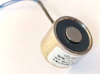
Before proceeding with this Fidget Spinner Electricity Generator project, since we are using an electromagnet lets understand how it works. The one that we are using in our project is a 12V 0.25A (more technical spec will be discussed later) electromagnet. So obviously, if we supply a 12V it will consume around 0.25A and produce a magnetic field (B) which will attract any metal piece in its surrounding area. This magnetic field is produced because the current flows through the coil which is inside the electromagnet and as we know according to Faraday's law of induction, all current carrying conductors produce a magnetic field around them. This magnetic field is concentrated at a particular point due to the coil arrangement and hence it’s capable of attracting metal. But this is not how we want it to work here.
Keeping the same faradays law in mind, we should be able to also generate current by creating a varying magnetic field near the electromagnet so that it acts as a generator. So to create this varying magnetic field we will use neodymium magnets with a fidget spinner.
Electricity Generator Project set-up:
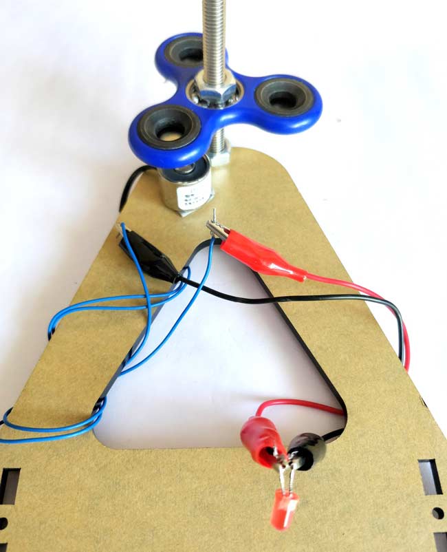
The set-up for this is relatively simple, you just have to place the neodymium magnets over the fidget spinner (as shown below) and place it directly over the electromagnet.

The neodymium magnets are very powerful and will try to get attracted to the electromagnet if you are spinning it with the free hand. Hence use some arrangement to hold both of them intact. I used a nut and bolt arrangement for the same as shown in the picture below. Once that is done connect an LED to the output terminal of the electromagnet (no polarity) and you are ready for a spin.
Generating Electricity using Fidget Spinner to Glow an LED:
Our mini generator is ready for action. Just spin the fidget spinner with your hand and you should notice the LED glowing. The same can also be found at the video presentation at the end of this page. The faster you spin the brighter it glows. Spend some time and enjoy your output, later let’s analyse what is happening here.

Okay, now to get technical, let's analyse few stuff. You should have noticed the LED to glow not matter in which direction you rotate the spinner or in which polarity you connect the LED. This is because here the LED actually glows on AC voltage. What....?????
Yes, no generator is ever capable of producing DC voltage. When the voltage is produced in a generator its default voltage will be AC. Even in DC generators, the immediate voltage produced out of the stator is AC it is later then mechanically converted into DC using an arrangement called commutator.
Estimating the Flux Produced by Spinner:
So far so good, you can go ahead and give yourself a cookie for understanding things so far. But let's try figuring out few more things using some formulas.
The Electromagnet that used here is of model number ZYE1-P20/16 which has the following specification mentioned in its datasheet. (There are more, I have listed only the required ones)
Voltage: 12V
Current: 0.25A
Holding force: 2.5kg/cm2 or 25N
Centre diameter: 8mm
In order to find the number of turns of the coil inside, let’s use the formulae
F = ((NI) 2 × µ0 × a) / (2×g2)
Where,
F = Holding force in Newton
N = Number of turns, which we are intending to find
I = Current flowing through the electromagnet in Amps
µ0 = Magnetic constant, which is 4π×10-7
a = Area of attraction in m2
g = gap between the electromagnet and the metal in meters
In these we know the force from datasheet which is 25N, the current is 0.25A, and area of attraction is calculated using πr2 (where r is 8mm) which gives 0.125m2. Finally, the gap is 0.01m since the 25N is given for per cm distance.
Using the above value the number of turns in our electromagnet is calculated to be roughly around 715 turns. Now that we know the number of turns in our electromagnet we can use this information to find the Magnetomotive force (mmf) that is being produced by the spinner when it rotates with the magnets.
MMF = I × N
Where, I is the current and N is the number of turns.
The current flowing through the LED could be approximated to 20mA.
MMF = 0.02 * 715
    = 14.3 At
This value of MMF is very very small than that compared with actual generators but for a fidget spinner with magnets, this is all we could get. Also, note that these calculations we performed just for understanding basis and is not intended to be used for analysis.
Hope you understood enjoyed the project and learned something useful from it. If you have any doubt use the comment section or the forums to get it resolved.
Comments
The answer to first question is YES. However I am not sure about the later one, because I cannot understand where exactly you are trying to add the coil.
Thank you for produce this quality writeup and video! Great for my kids learning. Can you post amazon links to the actual materials you used so I can purchase the correct items? great work - keep it up and will check out your other content.

would reducing the space between the coil and the magnets to about 1mm produce a more efficient field effect for the coil ??? & would adding a second coil in parallel to a 2:1 transformer and adding a slow discharge capacitor before the load regulate the output of light from the led ???