
Absence of light is what causes darkness, and we can automatically detect darkness or intensity of light using a Light Dependent Resistor (LDR). The circuit can be integrated with other electronics circuits or projects to control lights of a small bulb for automating lighting of something as large as whole city’s street lights. In this project, we will be making a simple Darkness Detector circuit. We have previously built few awesome projects using LDR and also made a light detector using LDR and Arduino Uno.
Components Required to build Darkness Detector
The darkness detection circuit is a very simple circuit and requires very few components, the complete list of components is mentioned below:
- LDR
- LED
- 1K ohm - Resistor
- 50k ohm - Resistor
- BC547 – BJT
- 9V battery
- Breadboard
Working Principle
The circuit is based around LDR which is also called a photoresistor. The resistance of LDR is dependent on the intensity of light. The 50k resistor and the LDR makes a voltage divider circuit. When the intensity of light falling on the LDR is high, it will have a higher resistance and hence the voltage divider will give a low output to the base pin of the BC547 BJT. BC547 is a NPN transistor, and when the BJT is in on-state, i.e. the emitter-base junction is in forward biased condition. The electronic path for our LED is completed and hence the LED illuminates.
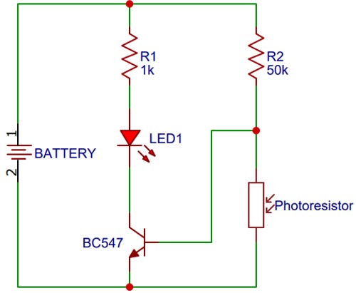
Circuit Diagram
For making the circuit, we connect a battery parallel to an LED with a 1K ohm resistor, the positive terminal or longer leg of LED is connected to the end of resistor and the negative terminal or shorter leg of LED is connected to the collector of our BJT. The emitter of BJT is connected to the negative terminal of the battery and the base of the BJT is connected to the junction connecting the LDR and a 50K ohm resistor. The other end of 50k resistor is connected to the positive rail of battery and the other end of the LDR is connected to the negative rail of the battery. For simplifying the connections, we have connected everything in a breadboard. The circuit diagram of the darkness detector is given below:

After connecting the components in a breadboard, we tested it by blocking the light falling on the LDR and the circuit worked perfectly. To see it in action, you can check the video at the bottom of the page.
Conclusion
A darkness detector circuit using LDR is a very simple circuit which can have many applications in the real world. This project requires very few components and is a cool system for your first electronics project. You can use this circuit as a subsystem and integrate it in your future projects. I hoped you enjoyed reading about this project and are ready to build your own darkness detector.
If you have any query, you can leave a comment in the section provided below or ask us in the Youtube video’s comment section.
