

AC LED driver circuits are overly popular due to the advancement of High current white LEDs. We already made a Transformerless LED driver circuit previously, but in that circuit, we used a dedicated LED driver IC like LNK304 to generate 13.6V 150mA of output current to power LEDs. But in this tutorial, we will not use any dedicated driver ICs, but we will make a 2.5 Watt AC LED driver circuit using basic components.
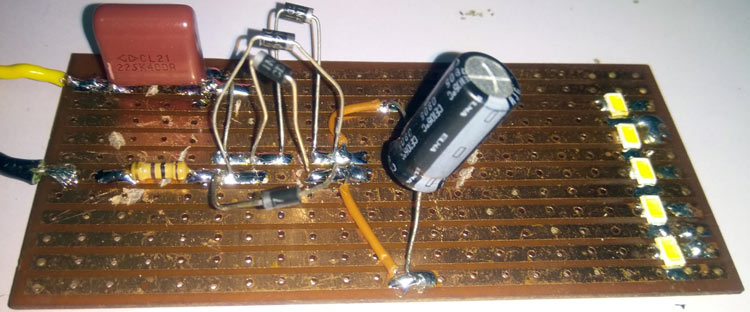
We will make the circuit in a perf board as High-Power LEDs require a heatsink (PCB copper area). The wattage of the circuit designed here is limited to 2.5 Watts but the wattage can be increased, however, it is always advisable to use proper driver circuitry for LED driver-related operations. There are lots of reasons for that.
A dedicated LED driver design provides accurate constant current as well as it will take care of the LED flickering issues which are an important parameter for proper LED drivers. However, the traditional LED lights or the LED bulbs available in the Indian markets need to be energy efficient. This is another reason to use a proper LED driver circuit to accumulate all of the above things. The circuit that will be demonstrated is only for low-cost AC LED bulb circuit with an output rating of 2.5 watts, it will need some tweaks if you are planning to use it in a product.
Warning: The circuit requires working with 230V Mains voltage, do not attempt to this without prior experience or professional supervision. Mains voltage can be lethal if not handled properly. You have been warned!
Bill of Materials
- 4x1N4007
- 100R resistor - 0.5 Watt rated
- 2 Meg resistor - 0.5 Watt rated
- 5xSMD LED 0.5 Watt (Vf - 3.2V with Forwarding current of 150-180mA)
- 2.2uF 400V Polyester Film Capacitor.
- 1000uF 35V Electrolytic Capacitor with a 105-degree rating
- Perf Board for soldering
230V AC LED Driver Circuit Diagram
The below image shows the complete AC to DC Led driver circuit Diagram. As you can see, it is a very simple circuit with very minimum components required. Taking a closer look, you can also notice that the circuit is very similar to the transformerless power supply that we built earlier.

Before describing the working of the circuit, it is essential to know the usability of the circuit. This circuit is highly dangerous and needs to be enclosed completely. This transformerless circuit does not use any isolation and there is an electric shock hazard, thus it cannot be used in any other applications where user interaction is required. However, the best way is to use it in led light related applications because users will be unable to touch any part of the circuit.
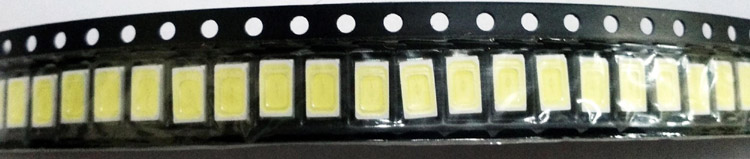
The LEDs shown in the above are specified with 0.5 watt cool white LEDs with a luminous flux of 57lm. The forward voltage is 3.2V minimum to the 3.6V maximum with a forward current of 120 to 150 mA. The package of the LEDs is 5730. Therefore, 5 LEDs in series will produce 2.5 Watt output and it will produce 285 lumens of light.
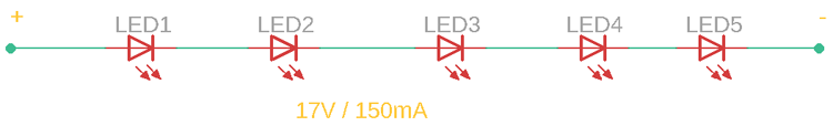
The 5 LEDs are connected in series. Thus the required voltage across the 5 LEDs strip will be 3.4V x 5 = 17V. As the LEDs are connected in series, the same quantity of current will flow through the circuit which is 130-150mA.
The Diode bridge that consists of 4 pcs 1N4007 rectifier diodes are used to transform the input AC to the Output DC and the Electrolytic 1000uF capacitor will provide smooth DC to the output.
On the other hand, the 100R 0.5Watt resistor is used to limit the current flow of the circuit. In this circuit, the major important components are the Polyester film capacitor with 1uF 400V rating and the 2 Meg 0.5Watt resistor. This Resistor and capacitor are connected in parallel with each other and both are connected in series with the 1N4007 diode bridge.
The capacitor is used to drop the AC voltage. Since, with AC that has a frequency, when connected with a capacitor, it will drop the voltage through its reactance. To calculate the current, one can use the formula-
I = V/X
where X is the reactance of the capacitor.
The reactance of the capacitor can be measured using the formula-
X = 1 / 2 x pi x f x C
where f is the AC frequency and C is the capacitance. By providing the value, as the Capacitor is 2.2uF in value, f is the 50 Hz frequency.
The reactance of the capacitor in 230V AC is,
= 1 / 2 x 3.14 x 50 x 0.0000022 = 1448 Ohms
Thus the output current will be:
I = 230/1448 = 159mA of current
Hence, one can increase the capacitance or add multiple capacitors in parallel to increase the output current.
Building and Testing AC LED Driver Circuit
The circuit is soldered in a perf board and soldered properly to provide adequate heatsink related supports.
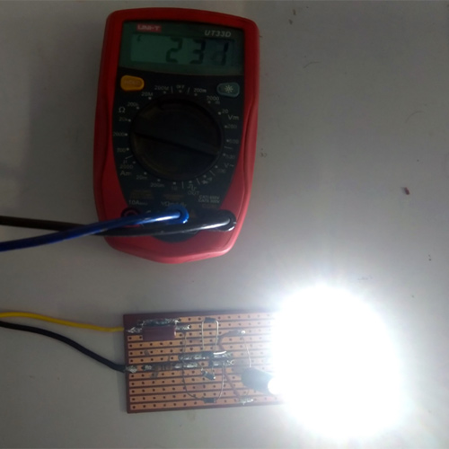
We have connected the circuit across a VARIAC and increased the input voltage to the 230VAC. The circuit started to produce output from 80VAC, you can find the LED’s turned on in the below image.
The complete working of the project can also be found in the video linked below. Hope you enjoyed the project and found it interesting to build your own. If you have any questions, please leave them in the comment section below. You can also write all your technical questions on forums to get them answered or to start a discussion.

The 100R resistor will blow up with 150mA. It will dissipate 2.25watts!!