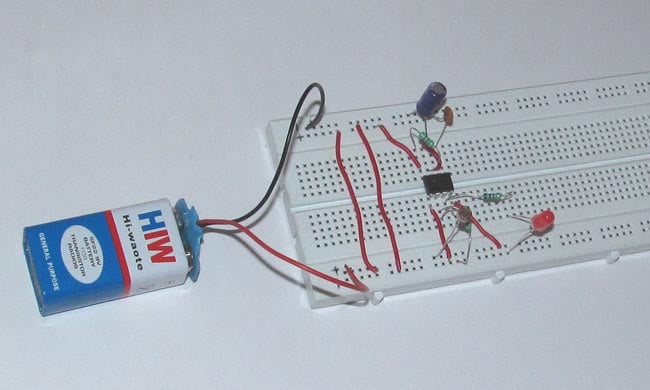
Here we have explained a dark detector circuit by using 555 timer IC and a LDR (Light Dependent Resistor) which senses the light in surroundings and if it does not find the light, it triggers the IC and glows an LED attached with the circuit. In place of LED we can also use a buzzer or speaker to use it as dark detector alarm. The concept of this LDR circuit is quite simple and based on the working of LDR. So lets first understand more about LDRs.
LDRs are a type resistors made from semiconductor materials to enable them to have their light sensitive properties. There are many types of LDRs but one of the most popular material used is cadmium sulphide (CdS). These LDRs or also known as photo resistors works on the principle of “Photo Conductivity”. Now what this principle says is , whenever light falls on the surface of the LDR (in this case) the conductance of the element increases or in other words the resistance of the LDR falls when the light falls on the surface of the LDR. This property of the decrease in resistance for the LDR is achieved because it is a property of semiconductor material used on the surface.
Here in this dark detecting LED circuit, LDR is configured with 555 timer IC in ASTABLE mode in such a way that 555 ASTABLE generates square wave when the light intensity goes below a certain level.
Circuit Components
- 555 Timer IC
- LDR
- Capacitors (100 nF, 100uf)
- Resistors (1k, 4.7k, 47k Ohm)
- LED
- 9V Battery
Circuit Diagram
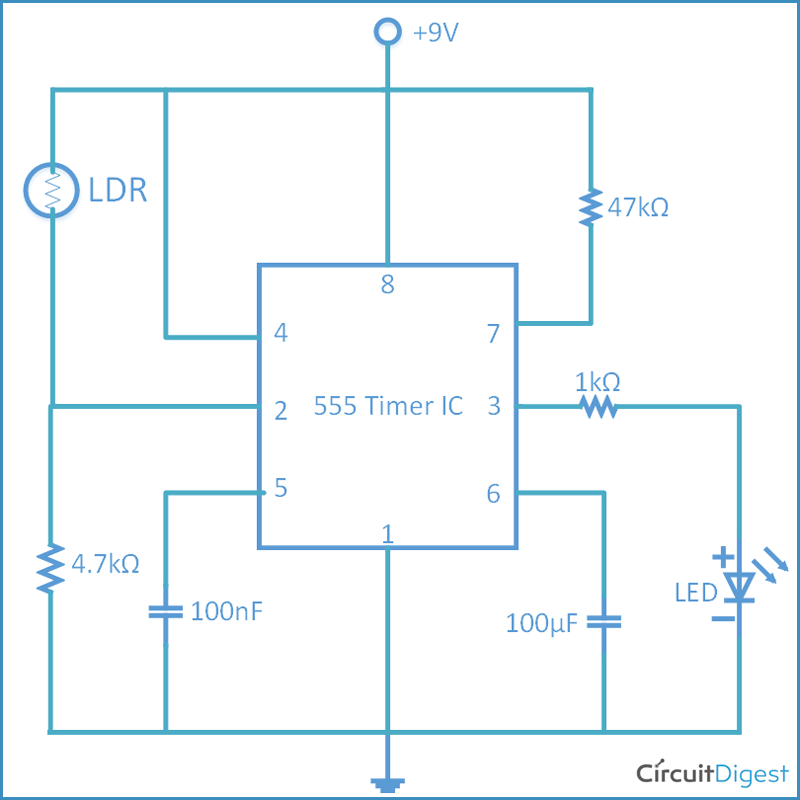
Above figure shows the circuit diagram of dark detecting LED. This circuit shows how we can convert a simple astable mode circuit to a “dark sensor”. We just need to add an LDR and a resistor in the circuit, then it simply works as dark detector. A general purpose LDR is used for sensing the light. When proper light is falling on the LDR its resistance is very low. When there is no light the LDR resistance increases. At this time the IC is triggered and glows the LED attached with the circuit.
Comments
Usually capacitance with larger values are electrolytic. Here it's 100microF
Check this to know more about capacitors: Different Types of Capacitors
In the circuit there should be a wire connecting pin 6 and pin 7. It is correct in the video but the circuit diagram given does not show this connection. Pls correct this.
Hope I have been of some help.
Thank you very much. It took me an hour trying to figure out what's wrong. The led would turn on when the light is off and it never turns off again.
hey do you think the circuit will work if I use 5v? if not then what will be the solution for the circuit to work on 5v
My connections seem right but the circuit doesn't detect darkness but rather the LED turn on after every 4 seconds. What could be wrong?
In the positive terminal what are commected!!!
In the circuit above what is the uses of the 100uf and 100nf capacitors. if I remove this 2 capacitors what will happen? please reply as soon as possible. I will make this as my project..


There seems to be 2 capacitors which are different ceramic and electrolytic, what are the unit values for each, which is the micro and which is the nano? and why did u specify there two different types of capacitors.