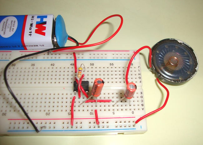
This is a 555 timer IC based fun circuit which generates a sound of loud clicking clock. It is quite simple circuit designed by wiring the 555 IC in astable mode.
Components Required
555 Timer IC
Capacitors - 2x 10µF
Resistors - 47k ohm
8 ohm Speaker
9v Battery
Breadboard and connecting wires
Circuit Diagram and Explanation
Ticking sound circuit is a good example of Astable mode of 555 timer IC. Here we are using a speaker which is used to convert electrical signal into sound. We are not using discharge PIN 7, and we have connected capacitor C2 to the OUTPUT PIN 3 of the 555 IC. Generally we used to connect the Capacitor to the voltage source, through resistors, but here we are connecting capacitor C2 directly to the OUPUT PIN 3, through a 47k ohm resistor. Capacitor will be charged through the output at PIN 3, when output PIN 3 will be HIGH. And capacitor C2 will be discharged to the Speaker when PIN 3 is LOW. When capacitor charge and discharge, speaker produce the sound of TIC-TIC.
Comments
Hi, this is what I need but who can explain a bit more to build this please ?


Thanks its exactly what i want.
Thanks again Noel