
There are many human identification systems that use signatures, fingerprints, voice, hand geometry, face recognition, etc. to identify persons but none of them can detect and recognize the persons in public areas such as airports, retail stores, and railway stations except the Face Recognition System.
Face recognition systems can, not only be used for security purposes to recognize the persons in public places but also can be used for attendance purposes in offices and schools.
In this project, we are going to build a Face Recognition System using ESP32-CAM which will also work as an ESP32-CAM Security system by recognizing the face of unauthorized persons. ESP32-CAM is a very small camera module with the ESP32-S chip. Using the ESP32-CAM module we can build a face recognition system without using any complex programming and any extra components. Face recognition can also be done using Raspberry Pi and Pi camera using OpenCV.
Introduction to ESP32-CAM
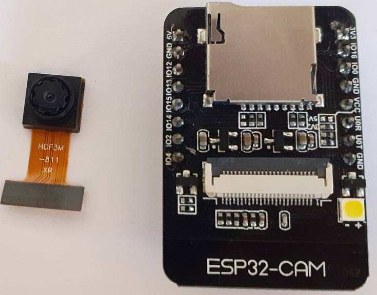
The AI-Thinker ESP32-CAM module comes with an ESP32-S chip, a very small size OV2640 camera and a micro SD card slot. Micro SD card slot can be used to store images taken from the camera or to store files. This ESP32-CAM module can be widely used in various IoT applications. It can be used as a face detection system in offices, schools and other private areas and can also be used as wireless monitoring, QR wireless identification, and many other IoT applications.
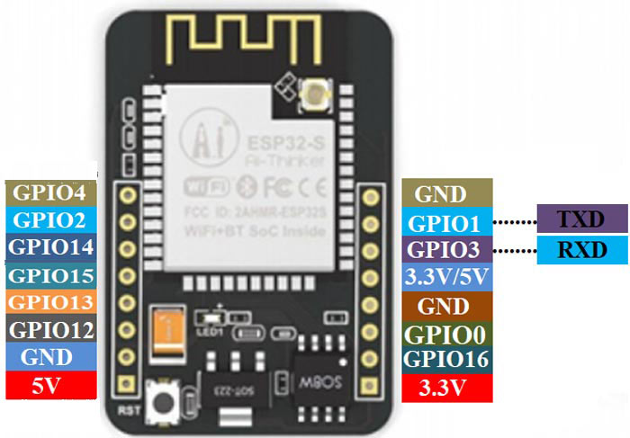
The ESP32-CAM module can be programmed with ESP-IDF or with Arduino IDE. ESP32-CAM module also has several GPIO pins to connect the external hardware. The ESP32-CAM doesn’t have a USB connector, so to program the module you need an FTDI board.
Features:
- The smallest 802.11b/g/n Wi-Fi BT SoC module
- Low power 32-bit CPU, can also serve the application processor
- Up to 160MHz clock speed, summary computing power up to 600 DMIPS
- Built-in 520 KB SRAM, external 4MPSRAM
- Supports UART/SPI/I2C/PWM/ADC/DAC
- Support OV2640 and OV7670 cameras, built-in flash lamp
- Support image Wi-Fi upload
- Support TF card
- Supports multiple sleep modes
- Embedded Lwip and FreeRTOS
- Supports STA/AP/STA+AP operation mode
- Support Smart Config/AirKiss technology
- Support for serial port local and remote firmware upgrades (FOTA)
Specifications:
- SPI Flash: Default 32Mbit
- RAM: 520KB SRAM+ 4M PSRAM
- Support TF Card: Max. 4G
- Support Interface: UART, SPI, I2C, PWM
- Image Output Format: JPEG, BMP, GRAYSCALE
- IO Port: 9
- Power Supply Range: 5V
Components Required
- ESP32-CAM
- FTDI Programmer
Circuit Diagram
To build ESP32 CAM Security Camera, we only need the ESP32 Camera module and FTDI programmer to program it.

ESP32-CAM doesn’t have a USB connector, so you need an FTDI programmer to upload the code into ESP32-CAM as shown in the figure above. Vcc and GND pin of ESP32 is connected with the Vcc and GND pin of the FTDI board. Tx of and Rx of ESP32 is connected with Rx and Tx of the FTDI board.
Note: Before uploading the code connect the IO0 to ground. IO0 determines whether the ESP32 is in flashing mode or not. When GPIO 0 is connected to GND, the ESP32 is in flashing mode.
|
ESP32-CAM |
FTDI Board |
|
3.3V |
VCC |
|
GND |
GND |
|
UOR |
TX |
|
UOT |
RX |
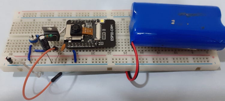
After programing the ESP32, I removed the FTDI board and connected the module to 3.3V power supply using a 7805 Voltage regulator. This is how the setup for ESP32 cam video streaming looks like:
Install ESP32 Board on Arduino IDE
Here ESP32-CAM is programmed using Arduino IDE. For that, we have to install the ESP32 add-on on Arduino IDE.
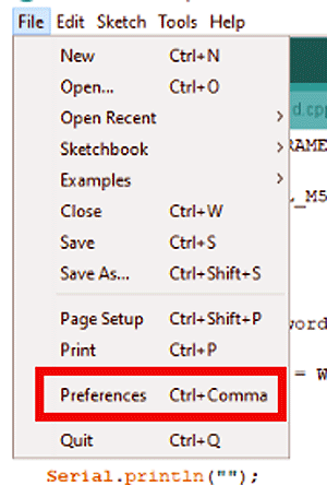
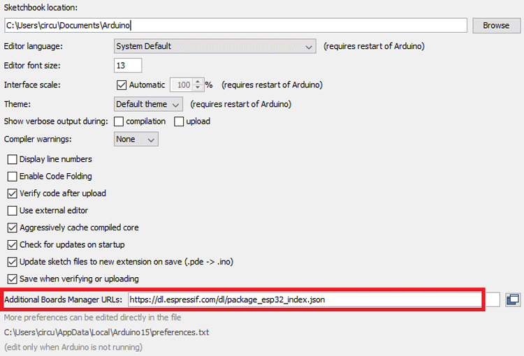
To install the ESP32 board in your Arduino IDE, go to File> Preferences
Now copy the below link and paste it into the “Additional Board Manager URLs” field as shown in the figure below. Then, click the “OK” button:
https://dl.espressif.com/dl/package_esp32_index.json
Now go to Tools > Board > Boards Manager
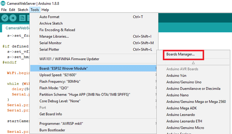
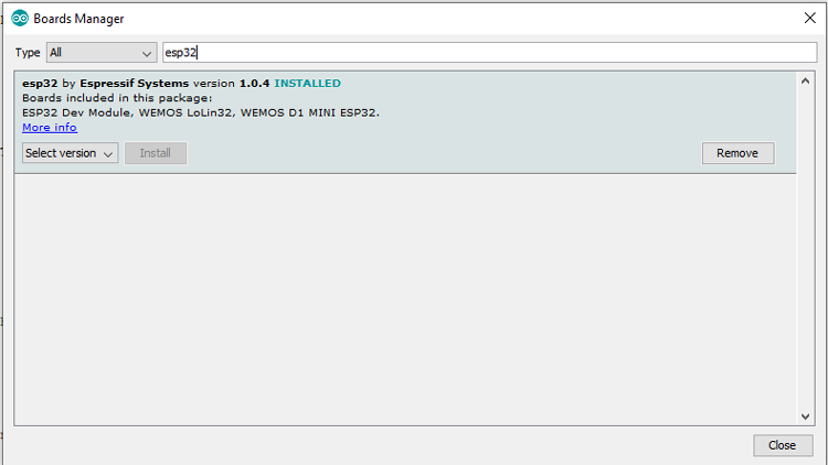
In Board Manager search for ESP32 and install the “ESP32 by Espressif Systems“.
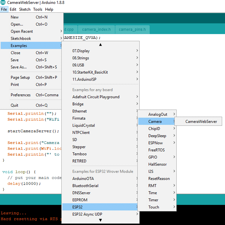
ESP32 Camera Webserver Code
We already have an example code from ESP32 cam video streaming and face recognition. Open the ESP32 example by using File > Examples > ESP32 > Camera and open the CameraWebServer example.
Before uploading the code, you need to enter your Wi-Fi name and password.
const char* ssid = "WiFi Name";
const char* password = "Password";
After that define the ESP camera module. In the code, they have defined 5 camera modules so uncomment the “CAMERA_MODEL_AI_THINKER” and comment rest of the modules.
Now the code is ready to upload.
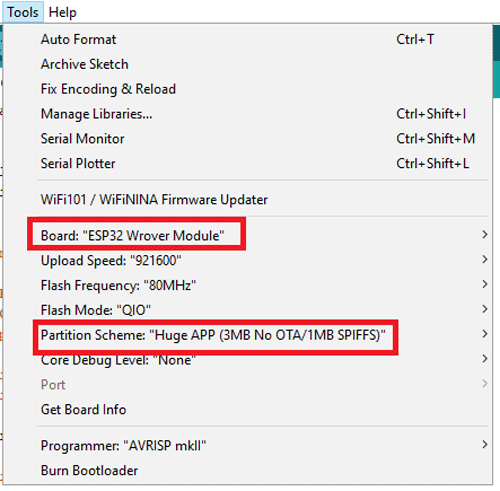
To upload the code, connect the FDTI board to your laptop and select the ‘ESP32 Wrover Module’ as your board. Also, change the other settings according to this picture:
Before uploading the code press the ESP32 reset button and then click on the upload button.
Note: If you get errors while uploading the code, check that IO0 is connected to GND and that you selected the right settings in the Tools menu.
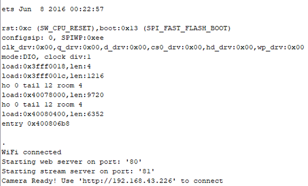
After uploading the code disconnect the IO0 and GND pin. Then open the serial monitor and change the baud rate to 115200. After that press the ESP32 reset button it will print the ESP IP address and port no on a serial monitor as shown below.
Now to access the camera streaming, navigate to your browser and enter your ESP IP address. It will take you to the streaming page. To start the ESP32 cam video streaming click on ‘Start Stream’ button at the bottom of the page
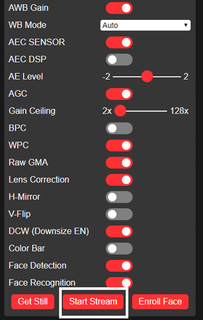
You can change the streaming quality by changing the ‘Resolution’ on the streaming page. You can also click the pictures by clicking the ‘Get Still’ button but this code doesn’t have the option to save the pictures.
After testing the video streaming now we will test the ESP32 cam face detection and recognition features. For that turn on the Face recognition and detection features from settings:
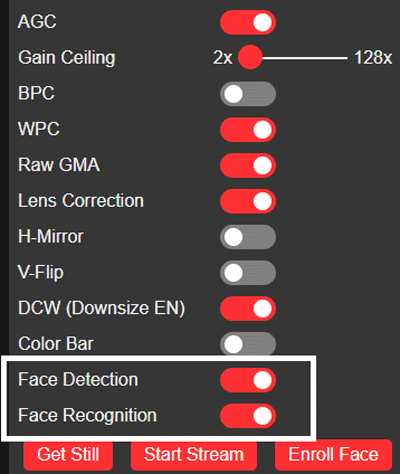
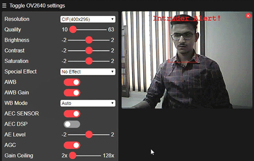
For the Face recognition first, you need to enroll a face. You can enroll in a new face by clicking on the ‘Enroll Face’ option. It takes several attempts to save the face. After saving the face it detects the face as subject 0 and now it can be used as a Security system by recognizing the face.
So this is how an ESP Camera Module can be easily configured for Video streaming and face recognition. Check small video footage below shot by ESP32 camera.
Complete code is given below and it can also be downloaded from here.
Complete Project Code
#include "esp_camera.h"
#include <WiFi.h>

// WARNING!!! Make sure that you have either selected ESP32 Wrover Module,
//  or another board which has PSRAM enabled

// Select camera model
//#define CAMERA_MODEL_WROVER_KIT
//#define CAMERA_MODEL_ESP_EYE
//#define CAMERA_MODEL_M5STACK_PSRAM
//#define CAMERA_MODEL_M5STACK_WIDE
#define CAMERA_MODEL_AI_THINKER
#include "camera_pins.h"

const char* ssid = "Galaxy-M20";
const char* password = "ac312124";

void startCameraServer();

void setup() {
  Serial.begin(115200);
  Serial.setDebugOutput(true);
  Serial.println();

  camera_config_t config;
  config.ledc_channel = LEDC_CHANNEL_0;
  config.ledc_timer = LEDC_TIMER_0;
  config.pin_d0 = Y2_GPIO_NUM;
  config.pin_d1 = Y3_GPIO_NUM;
  config.pin_d2 = Y4_GPIO_NUM;
  config.pin_d3 = Y5_GPIO_NUM;
  config.pin_d4 = Y6_GPIO_NUM;
  config.pin_d5 = Y7_GPIO_NUM;
  config.pin_d6 = Y8_GPIO_NUM;
  config.pin_d7 = Y9_GPIO_NUM;
  config.pin_xclk = XCLK_GPIO_NUM;
  config.pin_pclk = PCLK_GPIO_NUM;
  config.pin_vsync = VSYNC_GPIO_NUM;
  config.pin_href = HREF_GPIO_NUM;
  config.pin_sscb_sda = SIOD_GPIO_NUM;
  config.pin_sscb_scl = SIOC_GPIO_NUM;
  config.pin_pwdn = PWDN_GPIO_NUM;
  config.pin_reset = RESET_GPIO_NUM;
  config.xclk_freq_hz = 20000000;
  config.pixel_format = PIXFORMAT_JPEG;
  //init with high specs to pre-allocate larger buffers
  if(psramFound()){
    config.frame_size = FRAMESIZE_UXGA;
    config.jpeg_quality = 10;
    config.fb_count = 2;
  } else {
    config.frame_size = FRAMESIZE_SVGA;
    config.jpeg_quality = 12;
    config.fb_count = 1;
  }

#if defined(CAMERA_MODEL_ESP_EYE)
  pinMode(13, INPUT_PULLUP);
  pinMode(14, INPUT_PULLUP);
#endif

  // camera init
  esp_err_t err = esp_camera_init(&config);
  if (err != ESP_OK) {
    Serial.printf("Camera init failed with error 0x%x", err);
    return;
  }

  sensor_t * s = esp_camera_sensor_get();
  //initial sensors are flipped vertically and colors are a bit saturated
  if (s->id.PID == OV3660_PID) {
    s->set_vflip(s, 1);//flip it back
    s->set_brightness(s, 1);//up the blightness just a bit
    s->set_saturation(s, -2);//lower the saturation
  }
  //drop down frame size for higher initial frame rate
  s->set_framesize(s, FRAMESIZE_QVGA);

#if defined(CAMERA_MODEL_M5STACK_WIDE)
  s->set_vflip(s, 1);
  s->set_hmirror(s, 1);
#endif

  WiFi.begin(ssid, password);

  while (WiFi.status() != WL_CONNECTED) {
    delay(500);
    Serial.print(".");
  }
  Serial.println("");
  Serial.println("WiFi connected");

  startCameraServer();

  Serial.print("Camera Ready! Use 'http://");
  Serial.print(WiFi.localIP());
  Serial.println("' to connect");
}

void loop() {
  // put your main code here, to run repeatedly:
  delay(10000);
}
Comments
i like it .very good .Thank you very much
I cannot figure out how to do that using android.
Have any advice? Much appreciated.

Hi, congratulations for the article, if I had found it earlier I would have had less problems starting my cam.
Do you have any idea how to protect access to streaming and settings? I would like to use the cam by accessing it remotely, but if I connect it to the internet anyone can access it.
Thanks, see you soon