
Agree it!!! It has happened to all of us. Many times we misplace our keys and go searching for them everywhere in the house, and after a long search, we end up finding them with much distress. Now, the obvious solution here is to place your keys in their right place, but as engineers, what’s the fun in doing that. So, in this tutorial, we are going to build a simple IoT-based Smart Key Chain just using ESP8266-01, Buzzer, and Battery. Now in case if you can’t find your keys and you remember that you have attached an IoT keychain to your keys, so you take out your phone and open Chrome and open your Keychain Webpage. Then you click on the toggle button, and in moments, you hear a beep sound coming from your keychain and with this, you can easily track your keys.
As you can see from the image, we have built this circuit on PCB and we have used PCBONLINE to fabricate the PCB boards for this project. PCBONLINE is a PCB manufacturing and assembly service provider who has been in the industry since 1999. They can handle advanced PCBs with upto 24 layers adhering to ISO standards. The best part is that we can get high-quality industrial standard PCBs even for low volume orders and can also use their free PCB assembly and functional test services when ordering in bulk. We will explain more on how to use pcbonline later in this article , but for now, lets discuss about the design and working of our IoT based Key chain.
Components Required
- ESP8266-01
- AMS1117 3.3V Voltage Regulator
- Buzzer
- Lithium Polymer battery
- 2× 10µf Capacitor
Smart key Finder Circuit Diagram
The complete circuit diagram for the Esp8266 smart key chain is shown below. The schematic was drawn using EasyEDA.

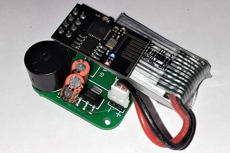
This complete setup will be powered by the Lithium polymer Battery and AMS117-3.3V is used to regulate 3.3V for the ESP8266-01 board. VCC and CH_PD pins of ESP8266-01 are connected to the output pin of AMS1117 while we connect the GND pin to the –ve rail of the battery. The positive terminal of Buzzer is connected to the GPIO2 pin of ESP8266 while the negative terminal of the buzzer is connected to the GND of ESP8266-01. Ok, so we are done with the connections. Now let’s have a look at the PCB Design.
Fabricating our Smart KeyChain using PCB Online
Now that we understand how the schematic works, we can proceed with building the PCB for our project. You can design the PCB using any PCB software of your choice. If you are a beginner who is just getting started in the world of PCB, we would recommend to try getting started with eagle for PCB Designing. If you want to skip the design processes, you can also download the Gerber file of this smart key finder project using the below link.
You can also check out our other PCB projects that we have previously built on circuit digest if you are interested. Now that our Design is ready, it is time to get them fabricated using the Gerber file. Getting your PCB fabricated from PCBONLINE is easy; simply follow the steps given below.
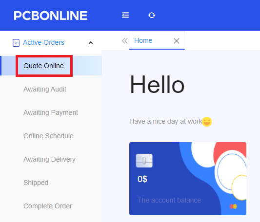
Go to https://www.pcbonline.com/ sign up if this is your first time. Then, go to the Active Orders tab and then click on ‘Quote Online’.
Now in the next window, enter the Gerber file, dimensions of your PCB, the number of layers, and the number of PCB you require.
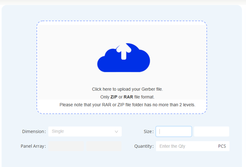
After entering the Gerber file, you can set a few additional parameters if required, like the material used track spacing, etc. but usually, the default values work fine. In the next step, you have to select the Build time, Shipping country.
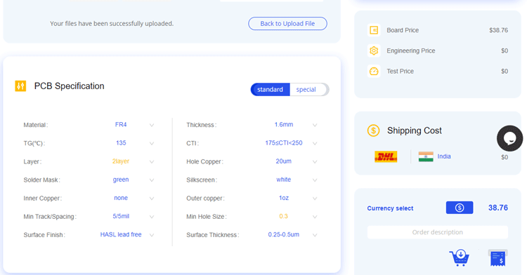
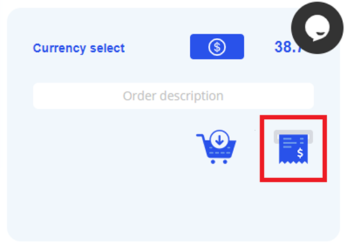
The final step is Checkout. To make sure the process is smooth; PCBONLINE first verifies all the details and Gerber file before proceeding with the payment. This way, you can be sure that your PCB is fabrication-friendly and will reach you as committed.
You can check your order status from the ‘Active Orders’ tab.
![]()
Assembling the Smart KeyChain Board
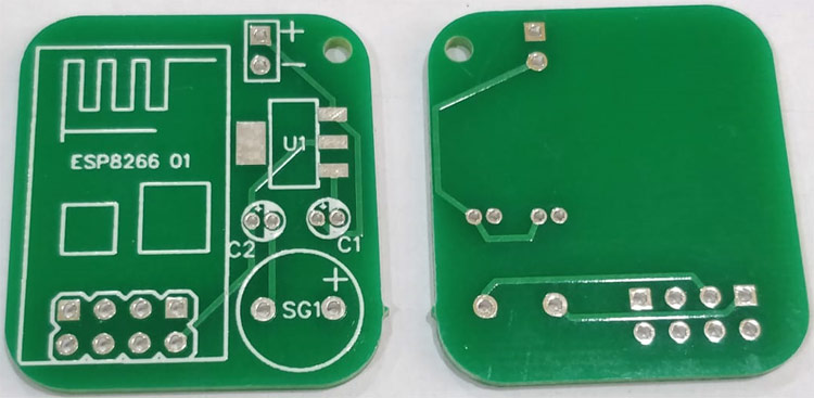
After a few days, we received our PCB from PCBONLINE in a neat package and as you can see below, the PCB quality was good as always. The top layer and bottom layer were seamlessly done with proper visa and track spacing. The top layer and the bottom layer of the board are shown below.
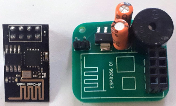
After making sure that the tracks and footprints were correct, I proceeded with assembling the PCB. The completely soldered board looked like as shown in the image below:
Smart Key Chain Code Explanation
Complete code for IoT-based Smart Keychain can be found at the end of the page. Here we are explaining the complete code line by line.
So as usual, let's start the code by importing all the required libraries. All the libraries that we are going to use in this code come pre-installed with ESP8266 board files. ESP8266WiFi library is used to connect NodeMCU to a Wi-Fi network.
#include <ESP8266WiFi.h>
#include <WiFiClient.h>
#include <ESP8266WebServer.h>
Then create a webserver object that listens for HTTP request on port 80
ESP8266WebServer server(80);
Define the ESP8266 pin where Buzzer is connected
const int buz_pin = 2;
In the next stage, enter Wi-Fi credentials like the user name and password for the Wi-Fi router to which your NodeMCU should connect with.
char ssid[] = "Wi-Fi Name";
char pass[] = "Wi-Fi Password";
The string variable ‘html_code’ contains a simple HTML code for creating a NodeMCU webpage.
String html_code =
"<!DOCTYPE html><html><head><style>.button {border: none;padding: 12px 40px;text-align: center;text-decoration: none;display: inline-block;font-size: 16px;margin: 4px 2px;cursor: pointer;}.button1 {background-color: black; color: white; border: 3px solid #1c1c1b;border-radius: 30px}body {text-align: center;}</style></head><body><h2>IoT Based Keychain</h2><p>Press the Button to Turn On/Off the Buzzer</p><form action=\"/BUZ\" method=\"POST\"><button class=\"button button1\">Press Me</button></form>";
The handleRoot() function is executed when we open the Webpage in the browser using the NodeMCU IP address. It sends the current buzzer state and a web page with a toggle button to webserver.
void handleRoot() {
server.send(200, "text/html", html_code + "Current state: <b>" + buzzing_state);
}
handleBUZ() is used to change the buzzer state if the button is pressed on the webpage. It adds a header to respond with a new location for the browser to go to the home page again.
void handleBUZ() {
buzzing_state = !buzzing_state;
server.sendHeader("Location","/");
server.send(303);
}
Inside the setup() function, we initialized the baud rate, defined the buzzer pin as an output, and then connect the module with the Wi-Fi using the Wi-Fi name and password.
Serial.begin(115200);
  delay(10);
  pinMode(buz_pin, OUTPUT);
  WiFi.begin(ssid, pass);
  while (WiFi.status() != WL_CONNECTED)
  {
    delay(500);
  }
  Serial.println("OK!");
The first function is used to call the 'handleRoot' function when a client requests URI (Uniform Resource Identifier) "/" while the second function is used to call the ' handleBUZ ' function when a POST request is made to URI "/ handleBUZ "
server.on("/", HTTP_GET, handleRoot);
server.on("/BUZ", HTTP_POST, handleBUZ);
Now in the next stage, we will read the buzzer state from the webpage and then change the GPIO pin state to turn on/off the buzzer.
void loop(void){
  server.handleClient();
  if (buzzing_state == true) {
    digitalWrite(buz_pin, HIGH);
    delay(400);
    yield();
    digitalWrite(buz_pin, LOW);
}

Programming ESP8266-01 for Smart Key Chain
Instead of using the FTDI board here, I am using Arduino Uno to program the ESP8266-01. The circuit diagram for programming ESP8266-01 using Arduino is given below:
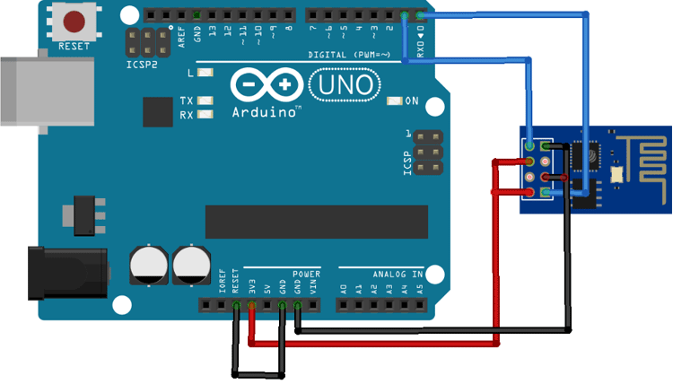
Connections for programming ESP8266 are as follows:
ESP8266-01 | Arduino Uno |
VCC | 3.3V |
GND | GND |
CH-PD | 3.3V |
RX | RX |
TX | TX |
GPIO-0 | GND |
GPIO-2 | Not Connected |
RST | Initially Not Connected. Before hitting upload connect RST to ground and remove after half a second |
Apart from these connections, connect the Reset pin of Arduino to GND to bypass the Arduino. It will disable Arduino and upload code directly to the ESP8266 board. Now power up the Arduino Uno and open the Arduino IDE. Select the “Generic ESP8266 Module” in Board. Now before clicking on Upload, we have to boot ESP-01 into programming mode. Ground the RST pin for a second. Now click on Upload in your Arduino IDE.
Testing our Smart Key Chain Finder
Now that we have assembled the PCB and uploaded the code on ESP8266-01, we are ready to test the keychain. For that power, the setup and wait until ESP connects to Wi-Fi, then get the ESP IP address. Now open your favorite browser and type in the IP address and search. It should open a page as shown below:
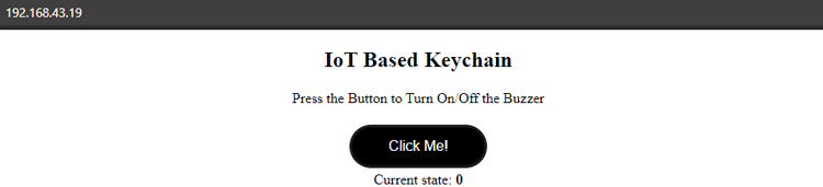
Click on ‘Click Me’ and the Buzzer we will make a sound until you click on the button again. The current state of the buzzer is shown below the toggle button. The complete working video and code for this project are given below. I hope you enjoyed building this project. If you have any questions, please leave them in the comment section.
Complete Project Code
#include <ESP8266WiFi.h>
#include <WiFiClient.h>
#include <ESP8266WebServer.h>
ESP8266WebServer server(80);
const int buz_pin = D2;
char ssid[] = "Galaxy-M20";
char pass[] = "ac312124";
String html_code = "<!DOCTYPE html><html><head><style>.button {border: none;padding: 12px 40px;text-align: center;text-decoration: none;display: inline-block;font-size: 16px;margin: 4px 2px;cursor: pointer;}.button1 {background-color: black; color: white; border: 3px solid #1c1c1b;border-radius: 30px}body {text-align: center;}</style></head><body><h2>IoT Based Keychain</h2><p>Press the Button to Turn On/Off the Buzzer</p><form action=\"/BUZ\" method=\"POST\"><button class=\"button button1\">Click Me!</button></form>";
boolean buzzing_state = false;
void handleRoot() {
server.send(200, "text/html", html_code + "Current state: <b>" + buzzing_state);
}
void handleBUZ() {
buzzing_state = !buzzing_state;
server.sendHeader("Location","/");
server.send(303);
}
void handleNotFound(){
server.send(404, "text/plain", "404: Not found");
}
void setup(void){
  Serial.begin(115200);
  delay(10);
  pinMode(buz_pin, OUTPUT);
  Serial.print("\n\nConnecting Wifi... ");
  WiFi.begin(ssid, pass);
  while (WiFi.status() != WL_CONNECTED)
  {
    delay(500);
  }
  Serial.println("OK!");
  Serial.print("IP address: ");
  Serial.println(WiFi.localIP());
  Serial.println();
  server.on("/", HTTP_GET, handleRoot);
  server.on("/BUZ", HTTP_POST, handleBUZ);
  server.onNotFound(handleNotFound);
  server.begin();
  Serial.println("HTTP server started\n");
}
void loop(void){
  server.handleClient();
  if (buzzing_state == true) {
    digitalWrite(buz_pin, HIGH);
    delay(400);
    yield();
    digitalWrite(buz_pin, LOW);
    delay(200);
    yield();
    delay(400);
    yield();
  }
}
Comments
can you upload BOM and CPL files along with the Gerber file, please?
Hello, if it is taken outdoors, it will leave the network connection. If this is the case, or in another house, will it also lose the connection to the network? If there is someone else’s network there, eap-01 will also be Unable to connect, because the code has set itself char ssid[] = "own network name";
char pass[] = "My network password"; This is the name and password of the network known to my home. I hope to see if there is any way, if there is an AP mode, the esp-01 spontaneous method can be connected to any other external network area, as long as the smart phone correspondingly enters the name and password, it can be used (of course, this is another code, enabled for AP mode)

I would have thought that the ESP8266, especially when constantly connected to WiFi, would take a lot of power, and would run down a coin cell quickly. I'd love to hear that I was wrong!
How much battery life do you get with this setup?