
Security is at most concern for anyone nowadays, whether it's data security or security of their own home. With the advancement of technology and the increasing use of IoT, digital door locks have become very common these days. Digital lock doesn’t require any physical key but it uses RFID, fingerprint, Face ID, pin, passwords, etc. to control the door lock. In past, we have developed many digital door locks applications using these various technologies. In this tutorial we build a Face ID controlled Digital Door lock system using ESP32-CAM.
The AI-Thinker ESP32-CAM module is a low-cost development board with a very small size OV2640 camera and a micro SD card slot. It has an ESP32 S chip with built-in Wi-Fi and Bluetooth connectivity, with 2 high-performance 32-bit LX6 CPUs, 7-stage pipeline architecture. We have previously explained ESP32-CAM in detail and used it to build a Wi-Fi door Video doorbell. This time we will use the ESP32-CAM to build a Face Recognition based Door Lock System using a Relay module and Solenoid Lock.
Components Required
- ESP32 CAM
- FTDI Board
- Relay Module
- Solenoid Lock
- Jumper Wires
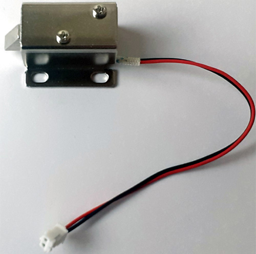
Solenoid Lock
A solenoid lock works on the electronic-mechanical locking mechanism. This type of lock has a slug with a slanted cut and a good mounting bracket. When the power is applied, DC creates a magnetic field that moves the slug inside and keeps the door in the unlocked position. The slug will retain its position until the power is removed. When the power is disconnected, the slug moves outside and locks the door. It doesn’t use any power in a locked state. To drive the solenoid lock, you would need a power source that can give 12V @ 500mA.
We previously used a solenoid lock to build an Arduino based RFID door lock.
Circuit Diagram
The Circuit Diagram for ESP32-CAM Face Recognition Door Lock System is given below:

The circuit above combined with an FTDI board, Relay Module, and Solenoid Lock. The FTDI board is used to flash the code into ESP32-CAM as it doesn’t have a USB connector while the relay module is used to switch the Solenoid lock on or off. VCC and GND pins of the FTDI board and Relay module is connected to the Vcc and GND pin of ESP32-CAM. TX and RX of the FTDI board are connected to RX and TX of ESP32 and the IN pin of the relay module is connected to IO4 of ESP32-CAM.
|
ESP32-CAM |
FTDI Board |
|
5V |
VCC |
|
GND |
GND |
|
UOR |
TX |
|
UOT |
RX |
|
ESP32-CAM |
Relay Module |
|
5V |
VCC |
|
GND |
GND |
|
IO4 |
IN |
Note: Before uploading the code, connect the IO0 to the ground. IO0 determines whether the ESP32 is in flashing mode or not. When GPIO 0 is connected to GND, the ESP32 is in flashing mode.
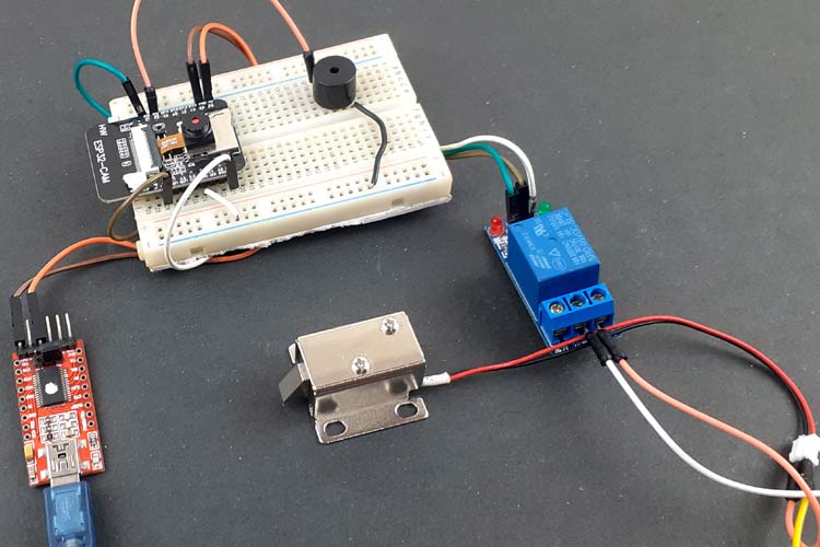
After connecting the hardware according to the circuit diagram, it should look something like below:
Install ESP32 Board on Arduino IDE
Here Arduino IDE is used to program ESP32-CAM. For that, first, install the ESP32 add-on on Arduino IDE.
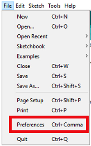
To install the ESP32 board in your Arduino IDE, go to File> Preferences.
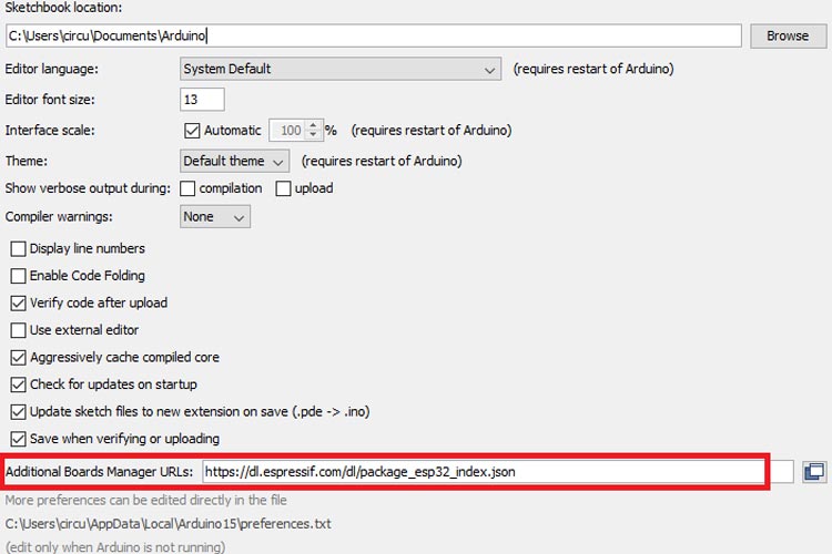
Now copy the below link and paste it into the “Additional Board Manager URLs” field as shown in the figure below. Then, click the “OK” button:
https://dl.espressif.com/dl/package_esp32_index.json
Now go to Tools > Board > Boards Manager
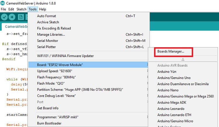
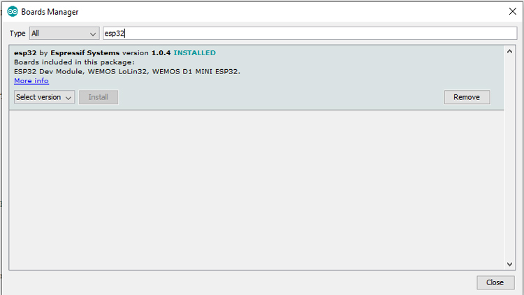
In Board Manager, search for ESP32 and install the “ESP32 by Espressif Systems“.
Code Explanation
We explained Face Recognition with ESP32 in the previous article; here we will modify the same code to control a solenoid door lock. The complete code is divided into four parts. One is the main code for the camera and relay module where the ESP32 locks or unlock the door according to face recognition, and the other three codes are for web page, camera index, and camera pins. Complete code is given at the end of this page. Here we are explaining some important parts of the code.
Begin the program by including all the library files.
#include "esp_camera.h"
#include <WiFi.h>
#include "camera_pins.h"
In the next line, uncomment the camera module that you are using with ESP32. In the code, five different camera models are defined. In this case, we’re using the AI-THINKER Model.
//#define CAMERA_MODEL_WROVER_KIT
//#define CAMERA_MODEL_ESP_EYE
//#define CAMERA_MODEL_M5STACK_PSRAM
//#define CAMERA_MODEL_M5STACK_WIDE
#define CAMERA_MODEL_AI_THINKER
After that, insert your network credentials in the following variables:
const char* ssid = "Wi-Fi Name";
const char* password = "Wi-Fi password";
Then define the pin where the relay module is connected. We will be using millis() function to lock the door after unlocking it in a defined interval of time, here it is 5 seconds.
#define relay 4
long prevMillis = 0;
int interval = 5000;
In the setup() function, initialize the Serial Monitor at a baud rate of 115200 for debugging purposes. Then in the next lines, define the pin mode for the relay module and also set the relay at a low position initially.
void setup() {
  Serial.begin(115200);
  pinMode(relay, OUTPUT);
  digitalWrite(relay, LOW);
Inside the loop() function, check if the face matches with the enrolled face. If yes, then unlock the door for 5 seconds and after 5 seconds lock the door again.
void loop() {
    if (matchFace == true && activeRelay == false){
      activeRelay = true;
      digitalWrite (relay, HIGH);
      prevMillis = millis();
    }
    if(activeRelay == true && millis()- prevMillis > interval){
      activeRelay = false;
      matchFace = false;
      digitalWrite(relay, LOW);
    }

Testing the ESP32-CAM Face Recognition Door Lock System
Finally to upload the code, connect the FDTI board to your laptop, and select the ‘ESP32 Wrover Module’ as your board. Also, change the other settings as shown in the below picture:
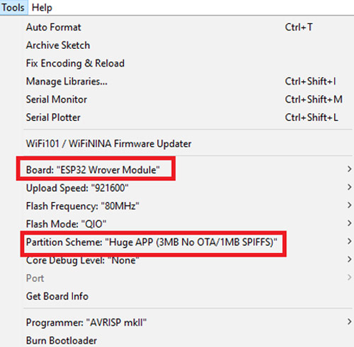
Don’t forget to connect the IO0 pin to GND before uploading the code and also press the ESP32 reset button and then click on the upload button.
Note: If you get errors while uploading the code, check that IO0 is connected to GND, and you selected the right settings in the Tools menu.
After uploading the code, remove the IO0 and GND pin. Then open the serial monitor and change the baud rate to 115200. After that, press the ESP32 reset button, it will print the ESP IP address and port no. on the serial monitor.
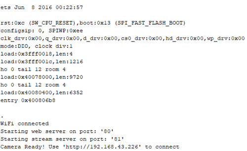
Now navigate to the browser and enter the ESP IP address that is copied from the Serial monitor to access the camera streaming. It will take you to the streaming page. To start the video streaming, click on the ‘Start Stream’ button at the bottom of the page.
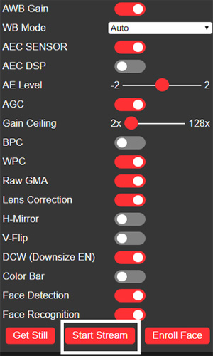
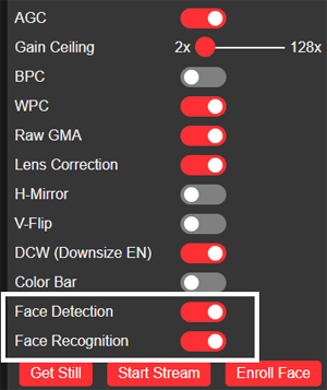
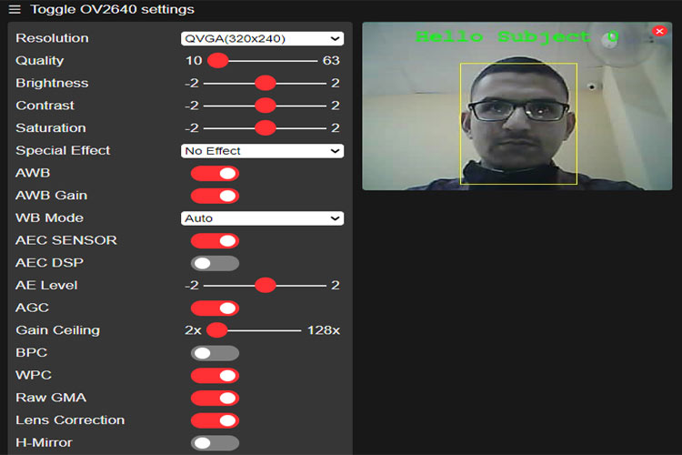
To recognize the faces with ESP32-CAM, first, we have to enroll the faces. For that, turn on the Face recognition and detection features from settings and then click on the Enroll Face button. It takes several attempts to save the face. After saving the face, it detects the face as subject 0 where zero is the face number.
After enrolling the faces, if a face is recognized in the video feed, ESP32 will make the relay module high to unlock the door.
So this is how the ESP32-CAM can be used to build a face recognition based security system. Complete Code can be downloaded from this link and is also given below along with a demonstration video.
Complete Project Code
#include "esp_camera.h"
#include <WiFi.h>
//
// WARNING!!! Make sure that you have either selected ESP32 Wrover Module,
//            or another board which has PSRAM enabled
//
// Select camera model
//#define CAMERA_MODEL_WROVER_KIT
//#define CAMERA_MODEL_ESP_EYE
//#define CAMERA_MODEL_M5STACK_PSRAM
//#define CAMERA_MODEL_M5STACK_WIDE
#define CAMERA_MODEL_AI_THINKER
#include "camera_pins.h"
const char* ssid = "Galaxy-M20";
const char* password = "ac312124";
#define LED_BUILTIN 4
#define relay 4
#define buzzer 2
boolean matchFace = false;
boolean activeRelay = false;
long prevMillis = 0;
int interval = 5000;
void startCameraServer();
void setup() {
  Serial.begin(115200);
  Serial.setDebugOutput(true);
  Serial.println();
  pinMode(relay, OUTPUT);
  pinMode(buzzer, OUTPUT);
  pinMode (LED_BUILTIN, OUTPUT);
  digitalWrite(LED_BUILTIN, LOW);
  digitalWrite(relay, LOW);
  digitalWrite(buzzer, LOW);
  camera_config_t config;
  config.ledc_channel = LEDC_CHANNEL_0;
  config.ledc_timer = LEDC_TIMER_0;
  config.pin_d0 = Y2_GPIO_NUM;
  config.pin_d1 = Y3_GPIO_NUM;
  config.pin_d2 = Y4_GPIO_NUM;
  config.pin_d3 = Y5_GPIO_NUM;
  config.pin_d4 = Y6_GPIO_NUM;
  config.pin_d5 = Y7_GPIO_NUM;
  config.pin_d6 = Y8_GPIO_NUM;
  config.pin_d7 = Y9_GPIO_NUM;
  config.pin_xclk = XCLK_GPIO_NUM;
  config.pin_pclk = PCLK_GPIO_NUM;
  config.pin_vsync = VSYNC_GPIO_NUM;
  config.pin_href = HREF_GPIO_NUM;
  config.pin_sscb_sda = SIOD_GPIO_NUM;
  config.pin_sscb_scl = SIOC_GPIO_NUM;
  config.pin_pwdn = PWDN_GPIO_NUM;
  config.pin_reset = RESET_GPIO_NUM;
  config.xclk_freq_hz = 20000000;
  config.pixel_format = PIXFORMAT_JPEG;
  //init with high specs to pre-allocate larger buffers
  if(psramFound()){
    config.frame_size = FRAMESIZE_UXGA;
    config.jpeg_quality = 10;
    config.fb_count = 2;
  } else {
    config.frame_size = FRAMESIZE_SVGA;
    config.jpeg_quality = 12;
    config.fb_count = 1;
  }
#if defined(CAMERA_MODEL_ESP_EYE)
  pinMode(13, INPUT_PULLUP);
  pinMode(14, INPUT_PULLUP);
#endif
  // camera init
  esp_err_t err = esp_camera_init(&config);
  if (err != ESP_OK) {
    Serial.printf("Camera init failed with error 0x%x", err);
    return;
  }
  sensor_t * s = esp_camera_sensor_get();
  //initial sensors are flipped vertically and colors are a bit saturated
  if (s->id.PID == OV3660_PID) {
    s->set_vflip(s, 1);//flip it back
    s->set_brightness(s, 1);//up the blightness just a bit
    s->set_saturation(s, -2);//lower the saturation
  }
  //drop down frame size for higher initial frame rate
  s->set_framesize(s, FRAMESIZE_QVGA);
#if defined(CAMERA_MODEL_M5STACK_WIDE)
  s->set_vflip(s, 1);
  s->set_hmirror(s, 1);
#endif
  WiFi.begin(ssid, password);
  while (WiFi.status() != WL_CONNECTED) {
    delay(500);
    Serial.print(".");
  }
  Serial.println("");
  Serial.println("WiFi connected");
  startCameraServer();
  Serial.print("Camera Ready! Use 'http://");
  Serial.print(WiFi.localIP());
  Serial.println("' to connect");
}
void loop() {
    if (matchFace == true && activeRelay == false){
      activeRelay = true;
      digitalWrite (relay, HIGH);
      digitalWrite (buzzer, HIGH);
      delay(800);
      digitalWrite (buzzer, LOW);
      prevMillis = millis();
    }
    if(activeRelay == true && millis()- prevMillis > interval){
      activeRelay = false;
      matchFace = false;
      digitalWrite(relay, LOW);
    }
}Comments
Sir how to declare Relay....in this program..
In this progrm there is error to declare relay
The rely is not declare im this scope
What's the component that's used between the jumper wires on the right. It's in black colour circular shaped. Please let me know as soon as possible.
Boolean variable matchFace declared within CameraWebServer.cpp. It will never become true and the code will not work as expected.

Dear.
Download link not work.