
From a small traffic signal controller to a complex high voltage switchyard, relays can be found everywhere. To put it in general, relays are just like any other switch which can either make or break a connection, that is it can either connect two points or disconnect it, therefore relays are commonly used to turn on or off an electronic load. But, this is a very generalized statement, there are many types of relays and each relay behaves differently as required for its application, one of the most popularly used relays is the electromechanical relay and hence we will focus more on that for this article. Despite the differences in construction, the basic working principle of a relay is the same, so lets discuss more on basic relay operation and take a deeper look into its construction
What is Relay?
A Relay is an electromechanical device that can be used to make or break an electrical connection. It consists of a flexible moving mechanical part which can be controlled electronically through an electromagnet, basically, a relay is just like a mechanical switch but you can control it with an electronic signal instead of manually turning it on or off. Again this working principle of relay fits only for the electromechanical relay.
There are many types of relay and each relay has its own application, a standard, and generally used relay is made up of electromagnets which in general used as a switch. Dictionary says that relay means the act of passing something from one thing to another, the same meaning can be applied to this device because the signal received from one side of the device controls the switching operation on the other side. So relay is a switch which controls (open and close) circuits electromechanically. The main operation of this device is to make or break contact with the help of a signal without any human involvement in order to switch it ON or OFF. It is mainly used to control a high powered circuit using a low power signal. Generally, a DC signal is used to control the circuit which is driven by high voltage like controlling AC home appliances with DC signals from microcontrollers.
Construction of Relay and its operation:
The following figure shows how a Relay looks internally and how it can be constructed,
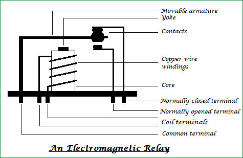
On a casing, a core with copper windings (forms a coil) winded on it is placed. A movable armature consists of a spring support or stand like structure connected to one end, and a metal contact connected to another side, all these arrangements are placed over the core such that, when the coil is energized, it attracts the armature. The movable armature is generally considered as a common terminal which is to be connected to the external circuitry. The relay also has two pins namely normally closed and normally opened (NC and NO), the normally closed pin is connected to the armature or the common terminal whereas the normally opened pin is left free (when the coil is not energized). When the coil is energized the armature moves and is get connected to the normally opened contact till there exists flow of current through the coil. When it is de-energized it goes to its initial position.
The general circuit representation of the relay is as shown in the figure below
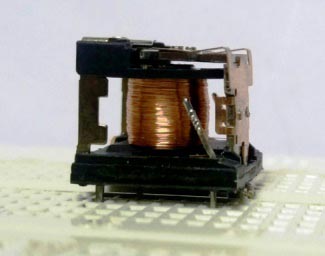
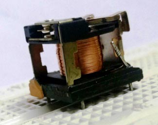
What is inside a Relay - Teardown
An electromechanical relay is basically designed using few mechanical parts like Electromagnet, a movable armature, contacts, yoke, and a spring/frame/stand, these parts are showing in the internal pictures of Relay below. All these are arranged logically to form into a relay.
Here we have explained the internal mechanical parts of a Relay:
Electromagnet: An Electromagnet plays a major role in the working of a relay. It is a metal which doesn’t have magnetic property but it can be converted into a magnet with the help of an electrical signal. We know that when current passes through the conductor it acquires the properties of a magnet. So, when a metal winded with a copper wire and driven by the sufficient power supply, that metal can act as a magnet and can attract the metals within its range.
Movable Armature: A movable armature is a simple metal piece which is balanced on a pivot or a stand. It helps in making or breaking the connection with the contacts connected to it.
Contacts: These are the conductors that exist within the device and are connected to the terminals.
Yoke:It is a small metal piece fixed on a core in order to attract and hold the armature when the coil is energized.
Spring (optional):Few relays don’t need any spring but if it is used, it is connected to one end of the armature to ensure its easy and free movement. Instead of a spring, a metal stand like structure can be used.

Relay Working Principle
Now let's understand how a relay works in a normally closed condition and normally open condition.
Relay in NORMALLY CLOSED condition:
When no voltage is applied to the core, it cannot generate any magnetic field and it doesn’t act as a magnet. Therefore, it cannot attract the movable armature. Thus, the initial position itself is the armature connected in normally closed position (NC).
Relay in NORMALLY OPENED condition:
When sufficient voltage is applied to the core it starts to create a magnetic field around it and acts as a magnet. Since the movable armature is placed within its range, it gets attracted to that magnetic field created by the core, thus the position of the armature is being altered. It is now connected to the normally opened pin of the relay and external circuit connected to it function in a different manner.
Note: The functionality of the external circuit depends upon the connection made to the relay pins.
So finally, we can say that when a coil is energized the armature is attracted and the switching action can be seen, if the coil is de-energized it loses its magnetic property and the armature goes back to its initial position.
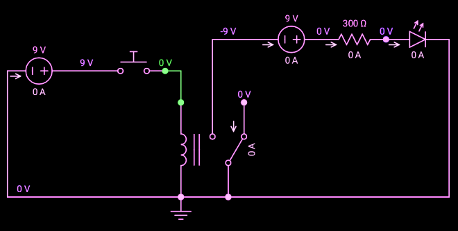
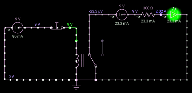
You can check the live working of the Relay in below given animation:
Different Types of Relay:
Other than the Electromagnetic relay there are many other types of relays that work on different principles. Its classification is as follows
Types of Relay Based on the principle of operation
-
Electrothermal relay:
When two different materials are joined together it forms into a bimetallic strip. When this strip is energized it tends to bend, this property is used in such a way that the bending nature makes a connection with the contacts.
-
Electromechanical relay:
With the help of few mechanical parts and based on the property of an electromagnet a connection is made with the contacts.
-
Solid State relay:
Instead of using mechanical parts as in electrothermal and electromechanical relays, it uses semiconductor devices. So, the switching speed of the device can be made easier and faster. The main advantages of this relay are its more life span and faster switching operation compared to other relays.
-
Hybrid relay:
It is the combination of both electromechanical and solid-state relays.
Types of Relay Based on the polarity:
-
Polarized relay:
These are similar to the electromechanical relays but there exists both permanent magnet and electromagnet in it, the movement of the armature depends on the polarity of the input signal applied to the coil. Used in telegraphy applications.
-
Non-polarized relay:
The coil in these relays doesn’t have any polarities and its operation remains unchanged even if the polarity of the input signal is altered.
Pole and Throw combinations:
Switches can also be classified based on the number of pole and throw combinations. A pole can be considered as an input terminal and a movable part connected to it, whereas a throw can be considered as an output terminal. Its classification is as follows
Single pole, single-throw Relay (SPST):
It consists of only one pole and one throw. Generally, the path is either closed or opened (remains untouched to any terminal). A push button is the best example of this type. When we push the button, the contact is in the closed position and when released the contact is in the open position, which can be understood from the below image.
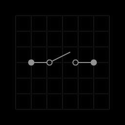
Single pole, double throw Relay (SPDT):
This type of switches consists of only one pole but has two throws. So, the contact is always made to either of the terminals. A slide switch can be considered as its example. The slider is always connected to either of the contacts i.e., a closed path always exists all the time if both the terminals are connected to a circuit.

Double pole, single throw Relay (DPST):
It has two poles and a throw. The contacts of it are either opened or closed which is done simultaneously. Toggle switch works on this property. When the switch is toggled from one position to another, both the contacts are moved simultaneously.
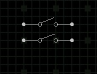
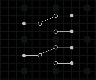
Double pole, double throw Relay (DPDT):
This type of switches has two poles but the individual pole has two throws. So, it is named as double throw and the switching action is done similarly and simultaneously for both the poles. A switch on a standard trimmer is of DPDT because while we are charging the trimmer and when the switch on the trimmer is in the ON state, it automatically stops charging means the switches are internally opened in the charging circuit.
Applications of Relay:
The applications of the relay are limitless, its main function is to control the high voltage circuit (230V circuit AC) with the low voltage power supply (a DC voltage).
- Relays are not only used in the large electrical circuits but also used in computer circuits in order to perform the arithmetic and mathematical operations in it.
- Used to control the electric motor switches. To turn ON an electric motor we need 230V AC supply but in few cases/applications, there may be a situation to switch ON the motor with a DC supply voltage. In those cases, a relay can be used.
- Automatic stabilizers are one of its applications where a relay is used. When the supply voltage is other than the rated voltage, set of relays sense the voltage variations and controls the load circuit with the help of circuit breakers.
- Used for the circuit selection if there exists more than one circuit in a system.
- Used in Televisions. An old picture tube television’s internal circuitry works with the DC voltage but the picture tube needs a very high AC voltage, in order to turn on the picture tube with a DC supply we can use a relay.
- Used in the traffic signal controllers, temperature controllers.
excellent . the circuit (diode) is very helpful.The analysis of left circuit with a resistor(small) and the right circuit is good.
excellent

Thank u for giving fanstastic experience on Relays..#CircuiDigest#Vamshidhar.