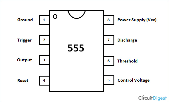
Monostable multivibrator (MMV) mode of 555 timer IC is also called Single shot mode. As the name indicates, only one state is stable and the other one is called unstable or quasi stable state. 555 timer IC remains in Stable state until the external triggering is applied. An external triggering is required for transition from Stable to unstable state. 555 IC automatically switches back to stable state after some time, this time, for which the 555 stays in quasi stable state, is determined by the time constant of RC network in the circuit. This external triggering is given by connecting the Trigger PIN 2 to the Ground using a PUSH button. Before going through below, you should know about 555 timer IC and its PINs, here is the short description about its PINs.

Pin 1. Ground: This pin should be connected to ground.
Pin 2. TRIGGER: Trigger pin is dragged from the negative input of comparator two. The comparator two output is connected to SET pin of flip-flop. With the comparator two output high we get high voltage at the timer output. If this pin is connected to ground (or less than Vcc/3), the output will be always high.
Pin 3. OUTPUT: This pin also has no special function. This is output pin where Load is connected.
Pin 4. Reset: There is a flip-flop in the timer chip. Reset pin is directly connected to MR (Master Reset) of the flip-flop. This pin is connected to VCC for the flip-flop to stop from hard resetting.
Pin 5. Control Pin: The control pin is connected from the negative input pin of comparator one. Normally this pin is pulled down with a capacitor (0.01uF), to avoid unwanted noise interference with the working.
Pin 6. THRESHOLD: Threshold pin voltage determines when to reset the flip-flop in the timer. The threshold pin is drawn from positive input of comparator1. If the control pin is open. Then a voltage equal to or greater than VCC*(2/3) (i.e.6V for a 9V supply) will reset the flip-flop. So the output goes low.
Pin 7. DISCHARGE: This pin is drawn from the open collector of transistor. Since the transistor (on which discharge pin got taken, Q1) got its base connected to Qbar. Whenever the output goes low or the flip-flop gets reset, the discharge pin is pulled to ground.
Pin 8. Power or VCC: It is connected to positive voltage (+3.6v to +15v).
Operation of Monostable Multivibrator mode of 555 timer IC:

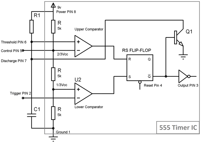
Operation is simple, initially 555 is in stable state i.e. OUPUT at PIN 3 is low. We know that Non-inverting end of Lower Comparator is at 1/3Vcc, so when we apply negative (< 1/3Vcc) voltage to the Trigger PIN 2 by connecting it to Ground (through a PUSH button switch), two things happens:
- First is, Lower comparator becomes HIGH and Flip flop gets Set and we get HIGH OUTPUT at PIN 3.
- And second thing is, Transistor Q1 becomes OFF, and Timing capacitor C1 get disconnected from the Ground and start charging though the Resistor R1.
This state is called the quasi stable state and remains for some time (T). Now when capacitor starts charging and reaches to the voltage slightly greater than 2/3 Vcc, voltage at Threshold PIN 6 becomes greater than the voltage at inverting end (2/3Vcc) of Upper comparator, again two things happens:
- Firstly, Upper comparator becomes HIGH and Flip flop gets Resets and the OUTPUT of the chip at PIN 3 becomes LOW.
- And secondly, Transistor Q2 becomes ON, and capacitor starts discharging to the ground, through the Discharge PIN 7.
So 555 IC automatically fall back to the stable state (LOW) after the time determined by the RC network. This duration of quasi stable state is given by the below formulae:
T= 1.1*R1*C1 Seconds where R1 is in OHM and C1 is in Farads.
So now we can see that MONOSTABLE mode has only one stable state and require a negative pulse at PIN 2, for the transition to Quasi stable state. Quasi stable state only remains for 1.1*R1*C1 seconds and then it automatically switch back to stable state. Remember one thing, while designing this circuit, that Trigger pulse at PIN 2 must be shorter enough to the OUPUT pulse, so that the capacitor gets enough time to charge and discharge.
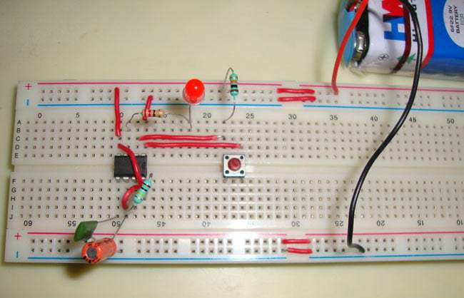
Here is the practical demonstration of the Monostable mode of 555 timer IC, where we have connected a LED to the output of the 555 IC. This LED will glow when we press PUSH button Switch and automatically switch OFF after T second. T is calculated below:
T= 1.1 *100k * 10 uf = 1.1 seconds
You can also calculate the T with this 555 timer monostable calculator
Above schematic diagram shows the 555 timer monostable multivibrator circuit. You can explore various applications based on monostable multivibrator in 555 timer circuits.
Comments
In this phrase:
And secondly, Transistor Q2 becomes ON, and capacitor starts discharging to the ground, through the
Discharge PIN 7.
should'nt it be Q1 instead of Q2 ? (there isn't any Q2)


Great regulator for circuit formation.