

Can Programming in DCS also lead to Tripping of HT Motors? In today’s case study I am going to present a case involving GRR (Grid Rotor Resistance) which is used in Slip ring induction motor. This type of problem is pretty rare in industries and hence would like to share the experience, so that the problem we faced will not be faced by others or can be avoided altogether.
In a cement plant, there was a HT Motor rated for 6.6 kV with 750 RPM which was used for operating a Fan. A modification was planned for this motor during breakdown which happened due to some malfunctioning of PLC. But during modification, the engineers overlooked one condition, which did not seem so big initially but then it tripped the complete plant. Before we get into the actual problem, let’s get few things straight by answering these questions.
Q1: What is GRR?
GRR stands for Grid Rotor Resistance, where a 3 phase resistance of the motor is changed on basis of changing few combination of power contactors.
Q2: Why do we need GRR?
GRR is used in speed control of Slip ring induction motor. It is commonly used at places where motor speed needs to be controlled (Mostly in Fans, Fan speed depends on Process requirement and Air flow required in a system)
Q3: What does the power contactors C1 to C6 signify?
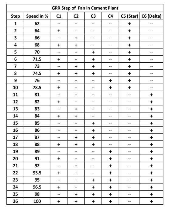
As mentioned earlier the Grid rotor resistance is controlled by changing few combinations of power contactors which are named from C1 to C6. Here C1, C2, C3, C4 are main power contactors, using which the rotor resistance can be changed. C5 is Star Contactor and C6 is Delta Contactor. If C5 is ON, it means GRR is in Star configuration and if C6 is ON, it means GRR is in Delta configuration. Both C5 and C6 will never be on at same time.
In GRR there is Local PLC, which controls the step of GRR, which works on the feedback from Power Contactor and Auxiliary Contactor. It also receives command from DCS and to increase or decrease rotor resistance, for controlling the speed of fan.
The team realized that this Fan PLC was creating some problem, due to which there was trouble in increasing or decreasing the speed of fan. The plant also tripped completely twice because of this problem. So, team decided to remove the PLC and take all the DI, DO and feedback to DCS and make a program just like PLC in their DCS, so as to remove the local PLC and reduce breakdown and malfunctioning.
Slip Ring Induction Motor tripping with Over Current Fault
Project was taken and was done during shutdown, every input and output was checked and configured. Just like PLC a program was made for DCS which removed the Local PLC. With the PLC bypassed, the team decided to take trial of fan during shutdown, to ensure that everything is right.
A trial was taken in offline mode; GRR was working fine and every step as was normal. Then we decided to take an online trial during which also the Motor started successfully. Current was normal, everything looked good. But then when we decided to take the motor to full RPM suddenly after one step the Motor tripped for over current.
What happened? Has the motor failed completely or was it just their modification that failed. Team was looking at each other. They did a Megger Test, inspected motors health and started again. The Motor started again normally but after that same step, it tripped again for over current. Atleast this time they got that something is wrong after 8th step of GRR, as till 8th step the motor runs fine and as soon as GRR goes to 9th step, the motor gets tripped.
Now the investigation started. GRR Resistance reading of every step and every phase was taken through micro-ohm meter. But the resistance was balanced for each step and every phase. GRR Step is given below.
Using Time delay as solution for over current problem:
This problem was not solved till 2 days. Both day trial taken 2 times and complete GRR and motor was checked. Till 8th step of GRR, everything is fine and as soon as it goes ton 9th step Motor trips. They asked in some other plants, one told them “increase the time delay between change of steps”.
On 3rd Day delay was given between changes of step of GRR. And to everyone surprise, it worked. Now the question was what time delay has done to GRR? Now we knew the problem was in delay. I looked again it into GRR 8th and 9th step and then realize what time delay has done.
How did time delay solve the over current problem?
In 8th Step C1, C2, C3 and C5 Contactors were ON i.e GRR was in Star configuration. Now as the command comes to GRR to go to 9th Step, Instead of the C3 contactor dropping first and then C4 Contactor picking up it was Picking up C4 Contactor first and then it was dropping C3 Contactor, due to which all the resistance were shorting momentarily and GRR was bypassed, which led to increase in Stator current and consequently tripping of Motor.
So the question was during Step change Contactor should drop first or Pick-up first? It was great learning, a simple PLC logic was tripping our HT motor.
Do share this with your colleagues in your Plant, Electrical Dept of other plants and your friends, It may save their Generator or Motor .
About the Author:
 Avinash Singh is an Electrical Engineer with over 11 years of rich experience in Electrical Maintenance, Installation, Testing, and Commissioning of all major Electrical equipments. He is specialized in bringing down Energy Cost of a Plant by reducing electricity bills and increasing energy efficiency. He also reduces plant breakdown cost by implementing proper maintenance activities during routine and shutdown. Through these Case Studies he shares his experience and challenges faced in his work routine with the readers of Circuit Digest.
