
Liquid Crystal Displays or more commonly known as LCDs are one of the most common electronic components which help us interact with an equipment or a device. Most personal portable equipment and even gigantic industrial equipment utilize a custom segment display to display data. For many portable consumer electronics, a segment LCD display is one of the biggest contributors to the overall cost of the device, hence designing a custom segment display can drive the cost down while also utilizing the display area in the most optimum manner. These displays have the lowest cost per piece, low power requirements, and a low tooling fee too.
At first thought, designing a custom segment LCD might look like a Herculean task, but trust me that it is easier than it seems. In this article, we have summarised and compared the display types and available technologies which are required to construct a custom segment LCD. We have also provided a flowchart that can act as a step-by-step guide while you design your own custom LCD. We have also provided the process we followed, a require gathering sheet we used for communicating our needs to the manufacturer, and a few other data and the quotation we received from the manufacturer.
Common Terminology used in Segment LCD Displays
Before we dive deep in, you should know about the common design terminologies associated with segment displays and what they mean.
Segments – It is the smallest unit that can be individually controlled, it can either be in the shape of a bar, dot, or icon.
Common Line – Electrical connection terminal connected to multiple segments
Segment Line – Electrical connection terminal which is connected to only one segment.
Icons: A silhouette of any shape can be placed on the glass which enhances the ability to display data. For example, a symbol of a heart can be made to denote heart rate or an icon for a low battery to show that the battery needs to be charged. Icons are counted as a single pixel or segment and can give a lot more details than similar-sized text.
LCD Duty Cycle – It denotes the time in which the segment is energized, it is given by the on-time by total time per frame.
LCD Bias – It denotes the number of different voltage levels used in driving the segments, static drives (explained later in this article) only have 2 voltage levels or 2 bias voltage while multiplex drives have multiple voltage levels. For example, 1/3 will have 4 bias voltages.
How Segment LCDs Work?
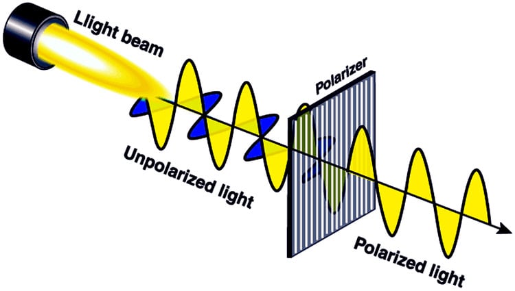
LCDs utilizes the light modulating properties of liquid crystals which can be observed by using polarizing filters. Polarizing filters are special materials that have their molecules aligned in the same direction. If the light waves passing through polarisers have the same orientation as the filter, then the molecules of lights are absorbed by the filter, hence reducing the intensity of light passing through it, making it visible.
In Layman’s language, when an electric current is applied to the electrodes, i.e. to the segment line and common line, it twists the Liquid Crystals w.r.t to the polarizing filter, obstructing the light in that particular area as shown in the figure below. Hence, that area becomes darker and prominent.
Why do you need Custom LCD Display?
A custom LCD is important for maximizing the efficiency of the display area by adding custom symbols and characters. It also helps in reducing the cost and improving energy efficiency of the product. A higher number of custom symbols and specified placement of numerical and alphanumerical characters make the display more informative and readable for the user. This makes it look better than the plain old boring displays we get in the market. Furthermore, we can specify the viewing angle, contrast, and other specifications which can increase durability or give a better value for money for our intended usage. A typical Custom Segment display is shown below, we will also show you how to design and fabricate the same further in the article.
The LCD display doesn’t emit any light of its own, therefore it requires an external source of illumination or reflector to be readable in dark environments.
Display Types
While designing a custom segment LCD display, we have the leverage of choosing a lot of parameters that affect the final product. From the color of the display to the illumination technique and color of illumination as well as the type of input pins. Some important considerations we need to take while designing a custom 7 segment display are - the type of display, i.e. positive or negative, illumination method, driving technique, polarising type, and connection method. All these design criteria are explained below:
Positive and Negative Displays:
Positive and negative displays can be easily distinguished by the colour of the background and characters. Some common differences between the positive and negative displays are:
|
Positive Display |
Negative Display |
|
|
|
|
Dark image on light background |
Light image on Dark Background |
|
Front and rear polarizers are perpendicular to each other |
Front and rear polarizers are aligned to each other |
|
Used in areas with high ambient light, the backlight can also be used. |
Used in areas with low ambient light, hence the backlights are often used. |
|
Background can be of multiple colours |
Pixels can be of multiple colours |
|
Can be used in any display technique |
Only possible with transmissive display |


So, which one should you choose? When the displays are to be used in areas with higher ambient light, we should select positive segment LCD display as it has better visibility than negative segment LCD displays without using a backlight.
Illumination Technique:
As we know that LED displays don’t emit any light, hence to illuminate it and make it visible in a dark environment, we can use different methods of illumination. The most common LCD Illumination methods are compared below:
|
|
Brightness |
Size |
Inverter required |
Power consumption |
Durability |
Life (in hours) |
|
LED |
Medium |
Small |
No |
Low |
High |
100,000 |
|
Incandescent |
High |
Medium |
No |
High |
Low |
10,000 |
|
Electroluminescent (EL) |
Low |
Small |
Yes |
Low |
High |
15,000 |
|
CCFL |
High |
Medium |
Yes |
|
Medium |
60,000 |
|
Fibre Optic |
Medium |
Small |
No |
High |
High |
100,000 |
For displays that need to be used for budget-friendly devices that should be small and rugged, LED lights are preferred for the displays due to the high durability and low cost of operations. For high brightness, CCFL and Incandescent lights can be used.
LCD Polarizers:
A polarizer film is the most important component of an LCD display, which makes it possible to display characters by controlling the light. There are 3 types of polarizers that can be used in the LCD display, the properties and difference are given below:
|
Transmissive Polarizer |
Reflective Polarizer |
Trans-reflective Polarizer |
|
|
|
|
|
In Transmissive Polarizer, the display is illuminated through backlight, embedded in the display |
In Reflective Polarizer, an outside source of light is used for illumination of the display |
Transflective Polarizer, can be illuminated through a backlight or the outside ambient lighting |
|
Contrast is better than transreflective polarizer but not as good as reflective polarizer |
It has the highest contrast ratio |
Contrast is not as sharp as the reflective polarizer |
|
Without a backlight it is difficult to be read |
Backlighting is not possible due to an opaque reflector |
It can be used with or without a backlight |
|
Consumes highest energy |
Consumes lowest energy |
Consumes low energy when backlight is turned off. |


If your products need to be used with a switchable backlight, then trans-reflective reflectors are best to be used for front reflectors. If the device has to be used without backlight, then we can select a reflective polarizer for the back-panel as it gives the best contrast ratio.
Passive and Active LCD Displays:
Displays can be categorized into two types, passive displays, and active display, passive displays are simpler to construct as they have 2 connections at each segment, the conductors comprise of an Indium Tin Oxide to create an image, whereas the active displays use thin-film transistors (TFT) arranged in a grid. The name is due to its ability to control each pixel individually.
|
|
|
Passive Display |
|
Active Display |
|
|
Twisted Nematic (TN) |
STN |
FSTN Film Super-twisted nematic |
TFT Display |
|
Cost |
Low |
medium |
High |
Very High |
|
Viewing angle |
Low |
Medium |
High |
Very High |
|
Contrast sharpness |
Low |
Medium |
High |
Very High |
|
Power Consumption |
Low |
Medium |
High |
High |
|
Operation temperature range |
-10 to 60 C |
0 to 50 C |
0 to 50 C |
|
If we need to display a fixed set of data, then we can select a passive display as it is cost-effective and energy-efficient.
Custom Segment LCD - Drive Methods:
It dictates how each segment is connected within the display. There are 2 drive methods, static drive, and Multiplex drive.
|
|
Static Drive |
Multiplex Drive |
|
|
|
|
|
Segment pins |
Individual pins for all segments |
Multiple segments can have the same pins |
|
Common pin |
Only one common pin in the LCD |
Multiple common pins |
|
Complexity of operation |
Easier to operate |
Complex to operate |
|
Most optimum application |
Optimum for LCDs with few segments |
Optimum for LCDs with a large number of segments |
|
Operating voltage |
Single operating voltage |
Multiple operating voltages |
|
Contrast Ratio |
Better contrast ratio than multiplex drive |
Lower contrast ratio than the static drive |


If your displays have fewer segments, then static LCD drive is preferred as it is easier to control and cheaper to construct, and has a better contrast ratio. But let’s say that if the number of segments in the display are more than 30-40 then a multiplex LCD drive should be preferred as it has multiple common pins, hence reducing the total number of pins required to drive the display.
LCD Interconnection:
LCD interconnections are used for connecting the devices with the LCD screen. They are mainly of 3 types that are:
|
Elastomer connection or Zebra strip
|
Minimum contact patch 0.5mm |
|
Pins
|
Minimum contact patch 1.5mm |
|
Flat Flex Cable
|
Minimum contact patch 0.28mm
|


Choosing a connector type!!! For the prototyping phase or if you need to connect your LCD display on a Microcontroller directly, a pin type connector is the best and most economical option you have. If you need to connect your LCD display in a final product with a high volume of production which also requires to be extremely durable, but at the same time should not take up a lot of space, a Flex type LCD Connector will work best for you
Viewing Angle Direction in LCD Displays:
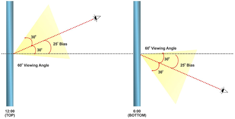
LCDs have limited viewing angles and when seen from an angle they lose contrast and are difficult to be observed. The viewing angle is defined by the angles perpendicular to the center of the display towards its right, left, up, and down which are denoted by the notations 3:00, 9:00, 12:00, and 6:00 respectively. The viewing angle of LCD can be defined as the angle w.r.t. to the bias angle at which the contrast of segments is legible.
To improve the viewing angle in an LCD, a Bias is incorporated in the design which shifts the nominal viewing angle with an offset. Another technique is to increase the Voltage, it affects the bias angle, making the display crisper when viewed from a direction.
For example, the viewing angle of a TN type TFT LCD is 45-65 degrees. Extra-wide polarising film (EWP) can increase the viewing angle by 10 degrees, using an O film polariser can make the viewing angles 75 degrees but these come at a cost of reduced contrast.
LCD Glare filter:
Anti-glare filters are bonded with the top polarising filters using adhesive. It improves the viewability by re-directing light waves so they don’t reflect back towards the viewer thus reducing glare. Newer materials are capable of reducing the front glare by up to less than 0.3%.
Control chip placement:
LCD Control chip or LCD driver chips can be mounted on the flex cable, display, or externally on a PCB. The placement of LCD control chip can affect the cost and size of the display. The 2 most common methods of chip placement are-Chip of Board (COB)and Chip on Glass(COG) which are described below:
|
Chip on board or surface mounted device
|
|
|
Chip on glass
|
|


COG can be used as it is cheaper and makes the assembly process simpler, but if the dimensions are a constraint, then the COB is also a viable option.
Case study for designing a custom LCD
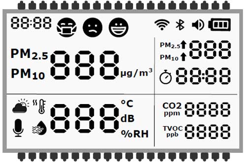
We planned to design an air quality monitoring system for which we needed a custom segment LCD panel for an air quality monitoring device. Our product needs to display the following data: 2.5-micron and 10-micron particulate matter (PM) suspended in the air; the units should be in parts per million (PPM). CO2 in the air in PPM along with total volatile organic compounds present in the air in parts per billion (PPB). To make the product more usable, we included time in 24-hour format, Temperature in ºC, Battery status, loudspeaker status, Bluetooth status, and Wi-Fi status. And for some personal touch, we also added how good the air quality in the room is by using 3 different smileys.
We realized that it was impossible to provide all these data in a generic LCD available in the market, thus decided to build a custom LCD for our project.
Steps of designing a custom LCD:
A step-by-step flowchart is shown below to walk you through each and every step of selecting components and getting your custom segment LCD manufactured.

We started by listing down our requirements and drew a mock-up of the display on paper. After finalizing the placement of all the segments and icons on the prototype sketch of the display, we then decided which all icons and segments have to be kept on for the whole time and which needs to be driven. Realizing that there are too many segments, characters and icons, hence we selected a multiplex drive with 8 common pins which helped us bring down the total pins from an estimated 180 pins to less than 40 pins.
Since the device was meant to be used inside houses and offices, which are more often than not well lit and protected from environmental conditions, we opted for a positive mode display. For superior contrast ratio and better viewing angle, we chose a Film Super Twisted Nematic Display (FSTN) with a drive condition of 1/8 Duty and bias of 1/4.
Usually, the displays are mounted at a height of 4.5 feet from the ground, thus the viewing direction was selected to be 12'O clock with an operating frequency of 64Hz. We selected a Transmissive polarizer for the front glass and a reflective polarizer for the rear glass so that the natural light can pass through the front panel and the display can achieve the maximum contrast without the need for backlighting and we opted for the pin type connectors as they are easy for prototyping and are suitable for harsh environment with a lot of vibrations and shocks which best suited our purpose.
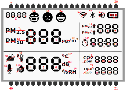
In the above image of a custom display design, we sent to the manufacturer, the red lines over multiple characters indicate that all these are considered as a single segment. For the sake of simplicity, we added test like T, S, U, B to denote Text, Symbols, Units, and Battery respectively. These characters were followed by numbers to simplify communication between us and the manufacturer. For example, if we needed any particular text or symbol to remain on, we can easily specify that to the manufacturer by using the corresponding text for that segment.
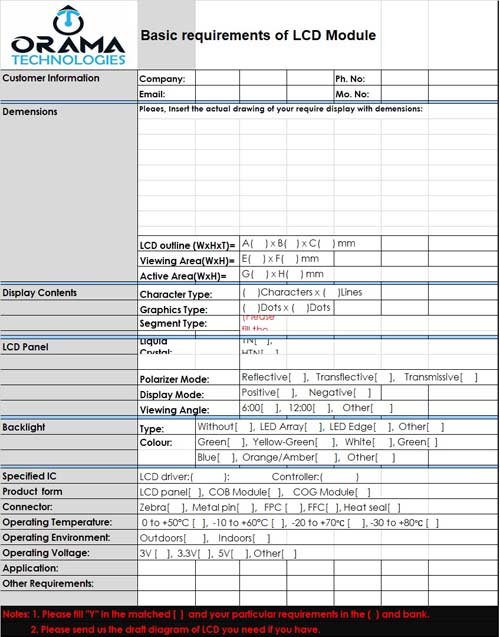
We mailed our requirements to multiple LCD manufacturers, (you will find a lot of LCD manufacturers on the Internet). Most LCD manufacturers have competitive pricing, and reply within a week. A sample requirement sheet is shown above which a customer needs to fill to specify all the details to the manufacturer.
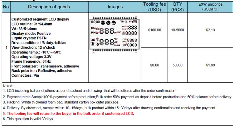
This is a sample Custom Segment LCD quotation we got from one of the manufacturers. As you can see, the cost is based on the quantity. Higher the quantity, lower the cost. Apart from the cost per quantity, there is one more component called tooling fees. Tooling fee is a one-time fee charged by the manufacturer. It is for the technical design, support, and customization of the product. Customization of PCB or tooling of LCD can drive the tooling price higher or lower.
The tooling time and cost depend on how detailed and accurate designs you sent to the manufacturer. They then send the exact dimensions and technical details of the product they will be manufacturing. Once you confirm the design, they manufacture and ship the product which might take 4-8 weeks to arrive depending on the size of the order and mode of transportation selected.
Conclusion:
A custom segment LCD can help you personalize your product while also saving the overall cost of your product. The whole process will take you around 2-3 months, which will include the designing phase, prototyping phase, and getting your custom segment LCDs delivered to your doorstep. Higher ordering quantity will reduce the cost per piece of each unit, thus driving down the cost of your final product.
