

The electric vehicle market is picking up quite rapidly across the globe. Estimates show that the number of electric vehicles on the road around the world will hit 125 million by 2030.Global market for Electric Vehicles (EV) and Hybrid. To control energy flow and optimize efficiency in HEV/EV powertrain subsystems such as Traction Inverters, On-Board Chargers (OBC), DC-DC converters, and Battery Management Systems (BMS), precise and accurate current measurement is essential. These high-voltage subsystems need to measure large currents at high common-mode voltages. For technical and regulatory reasons, the current measurements require isolation as well as very high performance in harsh automotive environments.
The typical configurations of electric vehicles in India are as below:
i) 2-wheeler
- Battery pack voltage = 48V , 72V
- 1kW , 2kW Motor
ii) 3-wheeler
- Battery pack voltage = 48V , 72V
- 2kW , 4kW Motor
iii) 4-wheeler and bus
- Battery pack voltage = 72V , 400V , 600V
- 20kW to 300kW
One of the key features to make an electric vehicle safe is to collect data and take quick feedback actions locally based on this data. One such data point which is very important and key to safety is the current flowing across various sub-systems of an electric vehicle.
We can split the current sensing in an Electric Vehicle broadly into 3 categories as shown below:
1. Real time Overcurrent protection
- Traction drives :
- Battery protection circuitry :
2. Current and power monitoring for System optimization
- Battery gauging
- System power consumption
- Power steering
3. Current measurement for closed loop circuits
- Motor drive application :
- DC/DC converters
Below is a high level overview of the different solutions from TI for current sensing applications. The Y axis is the common mode voltage of the rail through which current is being sensed and the X axis is the actual amplitude of the current being measured.
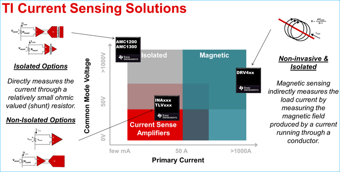
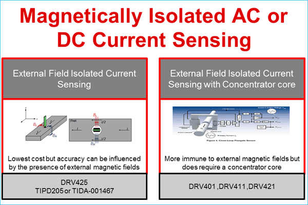
As shown in above figure current can be sensed through a voltage across a small shunt resistance or can be measured by measuring the magnetic field produced by the current while flowing through the conductor. At Ti we provide solutions for measuring current using both the methods mentioned above.
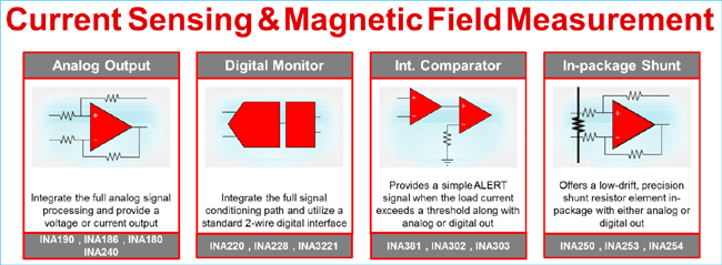
A list of solutions available from TI for current sensing application can be seen below:
Please note that the output of the current sensing amplifier can be either analog or digital. Based on the use case the engineer designing can decide on the mode of output to be used.
Lets look at each of the use cases of current sensor in a little more depth and look at some suitable solutions available from TI for the same.
1. Real time Over-current protection
This use case is generally seen in an EV from a safety prospective. As the batteries can discharge huge amounts of current during occurrence of a fault, having real time fault monitoring circuitry becomes very important. The speed and the accuracy of such a circuitry is the figure of merit the current sense amplifier. In some occasions as the uC has limited bandwidth, sampling the analog current value – converting into a digital value followed by a digital value comparison to detect overcurrent causes a huge delay in the protection circuitry. To tackle this problem TI has come up with current sense amplifier with integrated comparators whose threshold can be set and can be directly fed into the interrupt pin of the uC causing a huge reduction in overload of the uC.
Some of the solutions from TI for over current protection are:
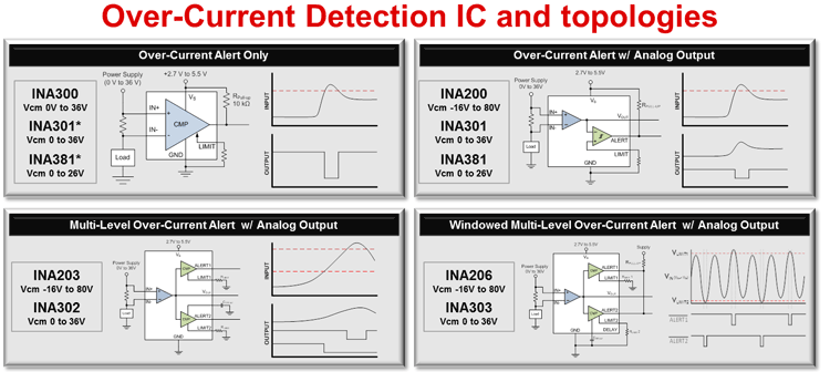
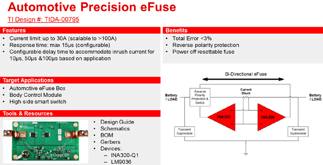
A very good example of this use case is using a current sense amplifier as an E fuse as shown below:
2. Current and power monitoring for System optimization
Current and power monitoring is usually implemented in electric vehicle systems to monitor the total current consumption from the battery and thus giving real-time information to the driver about the charge left in the battery of the vehicle using algorithms like coulomb counting. Besides the above use case current monitoring in vehicles Is utilized in different subsystems like the power steering, power windows and similar areas. TI has a broad portfolio when it comes to current and power monitoring.
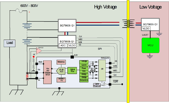
As mentioned above one of the key focus areas is to look into the current flowing in and out of the battery pack so as to count the coulombs and calculate the remaining battery life /charge. TI’s INA299 stands out for such an application due to the high level of integrity coupled with high precision and low quiescent current consumption. We can see a typical high level block diagram below of a BMS with the INA299. For more details and whitepapers please visit on to the product folder of INA299 on ti.com.
3. Current measurement for closed loop circuits
Due to the presence of multiple voltages available in an Electric vehicle, one finds a whole lot of combination of buck and boost converters presents in the power supply tree. Some of the very prominent power supply blocks in a typical Electric vehicle is the on board charger, BLDC (traction motor drivers), 48V to 12V converter etc. As the control loop in all these high wattage power supply is exercised using a uC, measurement of high accuracy, low latency current becomes of prime importance to implement peak current control loops. For such application current sensor with very high bandwidth is required to measure switching current , output current for the control to take quick actions .Another highlight of such current sensors which are used in controlling motor drives is the ability of the sensors to reject Common mode noise at high frequency ( PWM rejection ) .
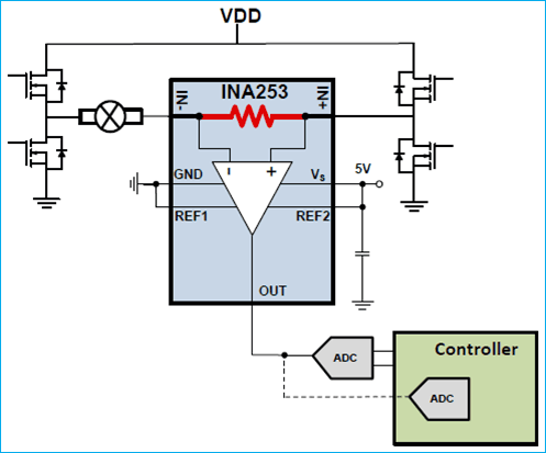
For examples INA253 excels in this application with its industry leading 93db CMRR even @ 50khz. Below is a typical schematic shown which is used for inline current sensing application
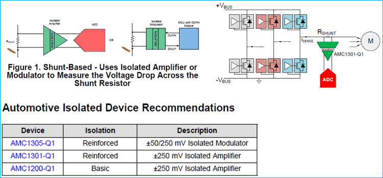
Texas Instruments offers best-in-class isolated amplifiers and isolated modulators that help achieve very accurate isolated current measurements over temperature when paired with high-precision shunts. TI has come up with a new range of isolated current sense amplifiers named as the AMC series which help the designed measure current with high accuracy with an isolation barrier of to the tune of 2kVrms.
TI has a good collection of deep drive trainings on “Getting Started with Current Sense Amplifiers” which shall help engineers learn how to maximize the performance achieved, when measuring current with a current sense amplifier. This is a series of short videos, each addressing a different topic.
Overall the training shall be broken into Three Sections
- The Basics
- Understanding Error Sources
- Advanced Topics
You can access all the TI training videos by following the link.
About the Authors
 Mr. Shreenidhi Patil is an analog application engineer in Texas Instruments who mainly focuses on Grid metering, upcoming EV market and EV charging stations.
 Mr. Mahendra Patel started his career in semiconductor industry with Texas Instruments 6 years ago. As a field engineer, he supports multiple customer and application in automotive sector. He enjoys working on designs related to Electric vehicles and automotive lighting.
