

A nominal lithium cell is rated for around 4.2V only, but in its applications like EV, portable electronics, laptops, power banks etc we require a lot higher voltage than its nominal voltage. This is the reason why designers combine more than one cell in series to form a battery pack of higher voltage values. As we know from our previous Electric Vehicle battery article, when batteries are combined in series the voltage value gets added up. For example when four lithium cells of 4.2V is connected in series the effective output voltage of the resulting battery pack will be 16.8V.
But you can imagine connecting many cells in series is like mounting many horses to a chariot. Only if all the horses run at the same speed the chariot will be driven with maximum efficiency. Out of four horses if one horse runs slowly, then the other three also has to reduce thier speed thus reducing the efficiency and if one horse runs faster it would eventually hurt itself by pulling the load of the other three horses. Similarly, when four cells are connected in series the voltage values of all the four cells should be equal to derive the battery pack with maximum efficiency. The method of maintaining all the cell voltages to be equal is called as cell balancing. In this article we will learn more about cell balancing and also briefly about how to use them on the hardware and software level.
Why do we need Cell Balancing?
Cell balancing is a technique in which voltage levels of every individual cell connected in series to form a battery pack is maintained to be equal to achieve the maximum efficiency of the battery pack. When different cells are combined together to form a battery pack it is always made sure that they are of the same chemistry and voltage value. But once the pack is installed and subjected to charging and discharging the voltage values of the individual cells tends to vary due some reasons which we will discuss later. This variation in voltage levels causes cell unbalancing which will lead to one of the following problems
The worst thing that can happen is thermal runaway. As we know lithium cells are very sensitive to overcharging and over discharging. In a pack of four cells if one cell is 3.5V while the other are 3.2V the charge will charging all the cells together since they are in series and it will charge the 3.5V cell to more than recommended voltage since the other batteries are still require charging.
When a lithium cell is overcharged even slightly above its recommended value the efficiency and life cycle of the cell gets reduced. For example a slight increase in charging voltage from 4.2V to 4.25V will degrade the battery faster by 30%. So if cell balancing is not accurate even slight overcharging will reduce the battery life time.
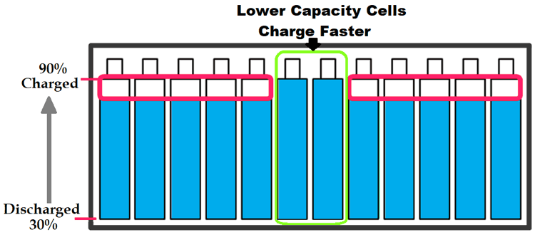
As the batteries in a pack get older few cells might be weaker than its neighboring cells. These week cells will be huge problem since they will charge and discharge faster than a normal healthy cell. While charging a battery pack with series cells the charging process should be stopped even if one cell reaches the maximum voltage. This way the if two cells in a battery pack get week they will charger faster and thus the remaining cells will not be charged to it maximum as shown below.
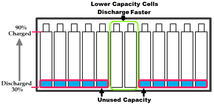
Similarly in the same case when the battery pack is being discharged, the weaker cells will discharge faster than the healthy cell and they will reach the minimum voltage faster than other cells. As we learnt in our BMS article the pack will be disconnected from load even if one cell reaches the minimum voltage. This leads to the unused capacity of the pack energy as shown below.
Accounting all the above possible disadvantages in consideration, we can conclude that a cell balancing would be mandatory to utilize the battery pack to its maximum efficiency. Still there are few applications where initial cost should be very low and battery replacement is not a problem in those applications cell balancing could be avoided. But in majority of applications including electric vehicles, cell balancing is mandatory to get the maximum juice from the battery pack.
What causes Cell unbalancing in battery packs?
Now we know why keeping all the cells balanced in a battery pack is important. But to address the problem properly we should know why the cells get unbalanced in the first hand. As told earlier when a battery pack is formed by placing the cells in series it is made sure that all the cells are in same voltage levels. So a fresh battery pack will always have balanced cells. But as the pack is put into use the cells get unbalanced due to the following reasons.
SOC Imbalance
Measuring the SOC of a cell is complicated; hence it is very complex to measure the SOC of individual cells in a battery. An ideal cell balancing technique should match the cells of same SOC instead of the same voltage (OCV) levels. But since it is practically not possible cells are matched only on voltage terms when making a pack, the variation in SOC might lead to change in OCV in due course.
Internal resistance variation
It is very hard to find cells of the same Internal resistance (IR) and as the battery age the IR of the cell also get changed and thus in a battery pack not all cells will have the same IR. As we know the IR contributes to the internal impedance of the cell which determines the current flowing though a cell. Since the IR is varied the current through cell and its voltage also gets varied.
Temperature
The charging and discharging capacity of the cell also depends on the temperature around it. In a huge battery pack like in EVs or solar arrays the cells are distributed over a waste areas and there might be temperature difference among the pack itself causing one cell to charge or discharge faster than the remaining cells causing an imbalance.
From the above reasons it is clear that we cannot prevent cell from getting imbalanced during the operation. So, the only solution is to use an external system that forces the cells to get balanced again after they get unbalanced. This system is called the Battery Balancing System. There many different types of hardware and software techniques used for battery cell balancing. Let is discuss the types and widely used techniques.
Types of Battery Cell Balancing
Cell balancing techniques can be broadly classified into the following the four categories which are listed below. We will discuss about each category.
- Passive Cell Balancing
- Active Cell Balancing
- Lossless Cell Balancing
- Redox Shuttle
1. Passive Cell Balancing
Passive cell balancing method is the simplest method of all. It can be used in places where cost and size are major constraints. The following are the two types of passive cell balancing.
Charge Shunting
In this method a dummy load like a resistor is used to discharge the excess voltage and equalize it with other cells. These resistors are called as bypass resistors or bleeding resistors. Each cell connected in series in a pack will have its own bypass resistor connected through a switch as shown below.

The sample circuit above shows four cells each of which is connected to two bypass resistors through a switch like MOSFET. The Controllers measures the voltage of all the four cells and turns on the mosfet for the cell whose voltage is higher than the other cells. When mosfet is turned on that particular cell begins to discharge through the resistors. Since we know the value of resistors we can predict how much charge is being dissipated by the cell. The capacitor connected in parallel with the cell is used to filter voltage spikes during switching.
This method is not very efficient because electrical energy is dissipated as heat in the resistors and the circuit also accounts of switching losses. Another drawback is that the entire discharge current flows through the mosfet which is mostly build into the controller IC and hence the discharge current has to be limited to low values which increases the discharging time. One way to overcome the drawback is to use an external switch to increase the discharge current as shown below
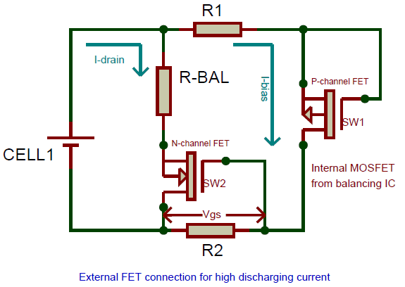
The internal P-channel MOSFET will be triggered by the controller which causes the cell to discharge (I-bias) through the resistors R1 and R2. The value of R2 is selected in such a way that the voltage drop occurring across it due to the flow of discharge current (I-bias) is enough to trigger the second N-channel MOSFET. This voltage is called the gate source voltage (Vgs) and the current required to bias the MOSFET is called as biasing current (I-bias).
Once the N-channel MOSFET is turned on the current now flows through the balancing resistor R-Bal. The value of this resistor can be low allowing more current to pass though it and thus discharging the battery faster. This current is called as drain current (I-drain). In this circuit the total discharge current is the sum of drain current and bias current. When the P-channel MOSFET is turned off by the controller the biasing current is zero and thus the voltage Vgs also gets zero. This turns off the N-channel MOSFET leaving the battery to get ideal again.
Passive cell balancing ICs
Even though the passive balancing technique is not efficient it is more commonly used because of this simplicity and low cost. Instead of designing the hardware you can also use few readily available IC’s like LTC6804 and BQ77PL900 from renowned manufacturers like Linear and Texas instruments respectively. These ICs can be cascaded to monitor multiple cells and saves development time and cost.
Charge Limiting
The charge Limiting method is the most inefficient method of all. Here only the safety and life time of the battery is considered while giving up on the efficiency. In this method the individual cell voltages are monitored continuously.
During the charging process even if one cell reaches the full charge voltage the charging is stopped leaving the other cells half the way. Similarly during discharging even if one cell reaches the minimum cut-off voltage the battery pack is disconnected from the load until the pack the charged again.
Although this method is inefficient it reduces the cost and size requirements. Hence it is used in an application where batteries could be often charged.
2. Active Cell Balancing
In Passive cell balancing the excess charge was not made used of, hence it is deemed to be inefficient. Whereas in active balancing the excess charge form one cell is transferred to another cell of low charge to equalize them. This is achieved by utilizing charge storing elements like Capacitors and Inductors. There are many methods to perform Active cell balancing lets discuss the commonly used ones.
Charge Shuttles (Flying Capacitors)
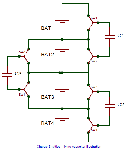
This method utilizes capacitors to transfer charge from high voltage cell to low voltage cell. The capacitor is connected through SPDT switches initially the switch connects the capacitor to the high voltage cell and once the capacitor is charged the switch connects it to the low voltage cell where the charge from the capacitor flows into the cell. Since the charge is shuttling between the cells this method is called as charge shuttles. The below figure should help you understand better.
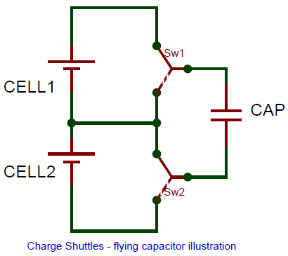
These capacitors are called the flying capacitors since the fly between the low voltage and high voltage cells carrying chargers. The drawback with this method is that charge can be transferred only between adjacent cells. Also it takes more time since the capacitor has to be charged and then discharged to transfer the charges. It is also very less efficient since there will be loss in energy during the charging and discharging of the capacitor and the switching losses also have to be accounted. The below image shows how the flying capacitor will be connected in a battery pack
Inductive converter (Buck Boost method)
Another method of Active cell balancing is by using inductors and switching circuits. In this method the switching circuit consists of a buck boost converter. The charge from the high voltage cell is pumped in the inductor and then discharged into the low voltage cell by using the buck boost converter. The below figure represents an Inductive converter with only two cells and single buck boost converter.
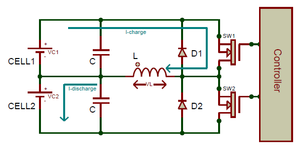
In the above circuit charge can be transferred from cell 1 to cell 2 by switching the MOSFETS sw1 and sw2 in the following manner. First the switch SW1 is closed this will make the charge from cell 1 to flow into the inductor with current I-charge. Once the inductor is fully charged the switch SW1 is opened and the switch sw2 is closed.
Now, the inductor which is fully charged will reverse its polarity and begin to discharge. This time the charge form the inductor flows into the cell2 with current I-discharge. Once the inductor is fully discharged the switch sw2 is opened and the switch sw1 is closed to repeat the process. The below waveforms will help you get a clear picture.
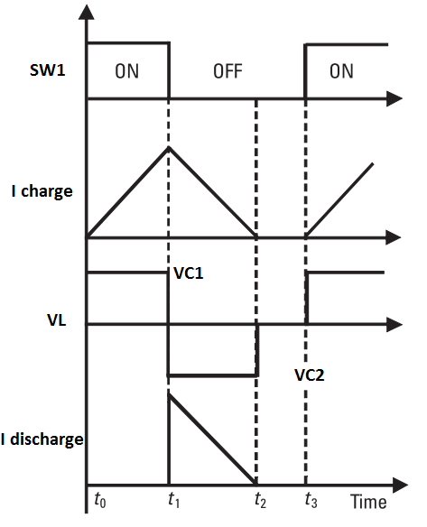
During the time t0 the switch sw1 is closed (turned on) which leads to the current I charge to increase and the voltage across inductor (VL) to increase. Then once the inductor is fully charged at time t1 the switch sw1 is opened (turned off) which makes the inductor to discharge the charge that it accumulated in previous step. When a inductor discharges it changes its polarity hence the voltage VL is shown in negative. When discharging the discharge current (I discharge) decrease from its maximum value. All this current enters the cell 2 to charge it up. A small interval is allowed from time t2 to t3 and then at t3 the whole cycle repeats again.
This method also suffers from a major disadvantage that charge could be transferred only from higher cell to lower cell. Also the loss in switching and diode voltage drop should be considered. But it is faster and efficient than the capacitor method.
Inductive converter (Fly back based)
As we discussed the buck boost converter method could only transfer charges form the higher cell to the lower cell. This problem can be avoided by using a Fly back converter and a transformer. In a flyback type converter the primary side of the winding is connected to the battery pack and the secondary side is connected to each individual cell of the battery pack as shown below
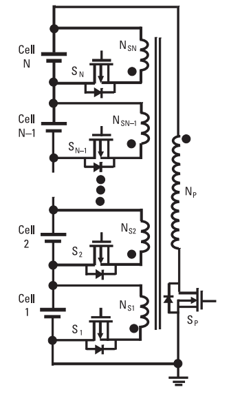
As we know the battery operates with DC and the transformer will have no effect until the voltage is switched. So to begin the charging process the switch on the primary coil side Sp is switched. This converts DC to pulsed DC and the transformer primary side is activated.
Now on the secondary side each cell has its own switch and the secondary coil. By switching the mosfet of the low voltage cell we can make that particular coil to act as a secondary for the transformer. This way the charge form the primary coil is transferred to the secondary coil. This causes the overall battery pack voltage to discharge into the weak cell.
The biggest advantage of this method is that any weak cell in the pack can be easily charged from the pack voltage and not particular cell is discharges. But since in involves a transformer, it occupies a large space and the complexity of the circuit is high.
3. Lossless balancing
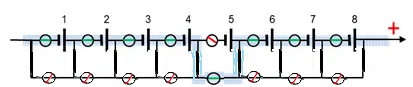
Lossless balancing is a recently developed method that reduces losses by reducing the hardware components and providing more software control. This also makes the system simpler and more easier to design. This method uses a matrix switching circuit which provides the capability to add or remove a cell from a pack during charging and discharging. A simple matrix switching circuit for eight cells is shown below.
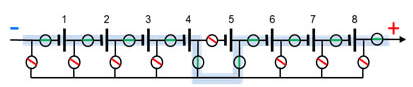
During charging process the cell which is of high voltage will be removed from the pack using the switch arrangements. In the above figure the cell 5 is removed from the pack by using the switches. Consider the red line circles to be open switches and the blue line circle to be closed switches. Thus the rest time of the weaker cells are increased during the charging process so as to balance them during charging. But the charging voltage has to be adjusted accordingly. The same technique can be followed during discharging also.
4. Redox Shuttle
The final method is not for hardware designers but for chemical engineers. In lead acid battery we do not have the problem of cell balancing because when a lead acid battery is overcharged it causes gassing which prevents it from getting over charged. The idea behind Redox shuttle is to try achieving the same effect on lithium cells by altering the chemistry of the electrolyte of the lithium cell. This modified electrolyte should prevent the cell from getting overcharged.
Cell Balancing algorithms
An effective cell balancing technique should combine the hardware to a proper algorithm. There are many algorithms for cell balancing and it depends on the hardware design. But the types can be boiled down to two different sections.
Measuring the Open circuit voltage (OCV)
This is the easy and most commonly followed method. Here the open cell voltages are measured for each cell and cell balancing circuit works to equalize the voltage values of all the cells connected in series. It is simple to measure OCV (Open circuit voltage) and hence the complexity of this algorithm is less.
Measuring Sate of charge (SOC)
In this method the SOC of the cells are balanced. As we already know measuring the SOC of a cell is a complex task since we have to account in the voltage and current value of the cell over a period of time to calculate the value of SOC. This algorithm is complex and used in places where high efficiency and safety is required like in aerospace and space industries.
This concludes the article here. Hope now you got a brief idea of what cell balancing is how it is implemented in hardware and software level. If you have any ideas or techniques do share them in the comment section or use the forums to get technical help.
Thank you david, your words are really encouraging.
There are lots of ICs from TI and Linear which makes cell balacning very easy, but I am not sure if they are available as modules. Also it depends on your battery arrangment and sensitiviety of your application.
Thanks,
Aswinth
Dear Ashwinth,
Great article!
Your articles have always been inspiring
I hope you would solve a query i have on Passive balancing
The passive balancing circuit shown in the above article particularly "Passive cell balancing using charge shunting bypass resistors" has put me in certain doubts
I would like to control the MOSFETs shown in the circuit using a microcontroller but I have come across a problem where the Vgs across every MOSFET higher up the voltage rail keeps on increasing making it impossible to control the MOSFET using logic level signals
Is there a solution to this?
Please suggest some reading to direct my research to
Regards
I am not an engineer but needed detailed information on cell balancing since I had to sit in on a meeting as an interpreter for product development using this method.
Your article has proven to be very effective, and easy to understand using everyday examples. I was able to perform my job with flying colors!
Thank you very much!
Great Article TBH..
Helped a great deal.
A hint for the Lossless Balancing Diagram:
The last 2 switches on the + side are too much.
An even better option to connect the "switches" would be to to do this
and not having to deviate the current over 2 side switches, but only one

Dearest Circuit Digest,
There are good articles and then there are GOOOOD articles like the one you have just written. The article calls upon one to really utilize the utmost of ones capability and knowledge, however, it is worth it.
It is educative too. I knew a little bit about cell balancing, however I did not know that it was such a science as presented.
As I am building IOT components, this is very valuable information for someone like me.
Are you aware of, if there are circuits available in trade, which does these cell balancing acts, such that one can simply buy those balancing circuits and apply power and woops, here we go?
Sincerely
David Svarrer