
Devoid of electromagnetic waves, an anechoic chamber (Figure 1) is a shielded room designed to provide an ideal environment for testing electronics. Anechoic means free from echoes—or non-reflective. These chambers are used in compliance testing. The surfaces of anechoic chambers are lined with carbon-based absorbing materials (Figure 2) and ferrite tiles in order to eliminate electromagnetic emanation, radiation, and reflection. Isolation from external interference enables design engineers to accurately test devices and electronic components like radar systems, antennas, sensors, and more. In an anechoic chamber, designers can also conduct a wide range of tests and measurements like thermal noise and military specification tests often conducted in certification labs.
Figure 1: Connected Development’s Over-the-Air (OTA) pre-compliance anechoic chamber used for antenna, radio, OTA, and RF testing. (Source: Connected Development)
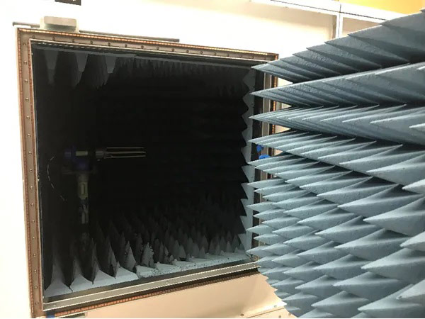
Figure 2: The inside of the chamber is lined with conductive carbon-coated material and is designed to make the chamber shielded and anechoic, meaning it is designed to prevent the signals from echoing or reflecting inside the chamber or from getting in from the outside–thus distorting RF measurements. (Source: Connected Development)
Electronic Device Certification Requirements
Regulatory and carrier requirements often present the need to test in RF and anechoic chambers. Any electronic device—wireless or wired—must meet certain governmental regulations, with requirements varying based on application and geographic location. Additionally, almost all products will need to meet government requirements for un-intentional emissions. Devices undergo anechoic or semi-anechoic chamber testing at an accredited certification lab to get certified or complete a Declaration of Conformity. Specifications may call out an Open Area Test Site (OATS) for testing but allow other calibrated chambers as alternatives. In these circumstances, it is best to undergo anechoic chamber testing rather than using an OATS site due to the controlled environment that anechoic chambers offer.
In the US, the Federal Communications Commission (FCC) requires that products meet FCC Part 15B if they contain a clock at 9kHz or higher, unless exempted (Title 47, part 15.05 Digital Device, 15.101). If the product includes a transmitter, additional radio-based testing is needed based on the spectrum the device operates in and other factors related to the product type.
For sales in Europe, the market requires a CE mark on the product. Part of the requirements contains an EMC directive or Radio Equipment Directive (RED), which has un-intentional emissions, spectrum efficiency, and immunity requirements.
What Is an Anechoic Chamber Used For?
Shielded from external interference, anechoic chambers offer a controlled environment for electronics testing. The following are key tests performed in anechoic chambers:
RF/Antenna Performance Testing: A key test performed in an anechoic chamber is RF/antenna performance testing. RF performance is critical, and the evaluation ties into final certification. An anechoic chamber enables measurements of transmitter performance, and designers can decide if any antenna circuit matching needs to be adjusted or if an antenna needs to be changed. The types of testing supported include RF testing and RF performance of devices for un-licensed radio areas like LoRa®, Wi-Fi, GPS, and BLUETOOTH®, and licensed areas like cellular.
Passive Antenna Pattern Testing: Anechoic chambers support passive antenna pattern testing for design, matching, or trimming an antenna. Testing the performance of antennas through the design phase is important, and in un-licensed certified modules, the antenna gain is limited by the certified module manufacturers’ limits or limitations presented by governmental bodies for the radio type and service. In cases where the antenna is designed into the PCB as a trace antenna, anechoic chamber testing can provide insights into the gain and efficiency of the design.
PTCRB/CTIA OTA Testing: In the US, cellular device approvals are generally required to meet OTA and Radiated Spurious Emissions (RSE) requirements set by carriers like AT&T and Verizon. OTA test methods are determined by certification programs such as PTCRB, CTIA, or the cellular carriers themselves.
Other Performance or Quality Testing: Other tests that can be performed in anechoic chambers include:
Pre-compliance testing throughout the development cycle to avoid costly re-work and redundancy in submission for final certification
Un-intentional radiated measurement testing
RSE testing for harmonics of the transmitter
OTA antenna testing
CE Immunity tests
How Is an Anechoic Chamber Constructed?
From small, mounted chambers to rugged military-grade chambers, anechoic chambers come in many different shapes and sizes. The size and weight of the device and frequencies to be investigated help determine the size and type of chamber needed (i.e., measuring an automobile vs. a cellular phone). The internal turntable needs to be able to handle the weight of the device and rotate freely. The distance between the device and the antenna needs to be large enough to measure down to the lowest frequency desired. Typically lined with carbon-based absorbing materials or ferrite tiles, anechoic chambers are constructed in one of two ways—fully anechoic or semi-anechoic:
Fully Anechoic Chambers
Fully anechoic chambers (Figure 3) have absorbing material, ferrite material, or both on all surfaces—floors included. The goal is to absorb all energy, allowing the test antenna to measure only the energy seen in a direct line from the product being tested. Fully anechoic chambers are used to test for emissions, immunity, antenna pattern, and transmitter and receiver testing–including OTA.
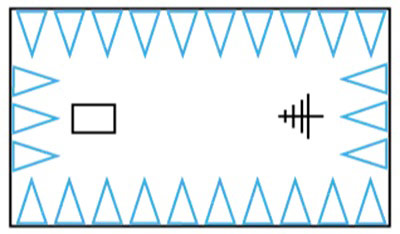
Figure 3: Diagram showing placement of absorbing material in a fully anechoic chamber. (Source: Connected Development)
Semi-Anechoic Chambers
Semi-anechoic chambers (Figure 4) have absorbing material, ferrite material, or both on the walls and ceiling. For some test areas, absorbing material is placed between the test antenna and the product being tested, but is not present on all surfaces. Semi-anechoic chambers are used to test for emissions immunity testing.
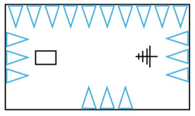
Figure 4: Diagram showing placement of absorbing material in a semi-anechoic chamber. (Source: Connected Development)
Conclusion
To ensure optimal performance and compliance with governmental regulations, electronics must undergo thorough testing. Anechoic chambers provide a means to take repeatable RF measurements and eliminate reflections and outside interference. Testing is supported for both unlicensed and licensed radios. Anechoic chamber testing provides detailed insights into the performance of devices. It ensures the device's antenna performance meets the needs of the device, addresses governmental compliance, and assists in troubleshooting design modifications.
About Author

"Darin Hatcher is a Certification Manager at Connected Development with previous experience as a Radio Characteristics and Regulatory Engineer. Darin specializes in radio access stack, radio characteristics, FCC, and 3GPP type approval. His expertise spans IoT M2M areas for Cellular (5G, 4G including Cat-M and NB-IoT, 3G and 2G), Wi-Fi, Bluetooth, GPS, and LoRa®. In his current role, Darin oversees the certification process and testing for government regulations, (FCC, ISED, CE) and carrier requirements (OTA, PTCRB, CTIA, AT&T, Verizon, etc.)"
Originally Posted on Mouser
