Introduction
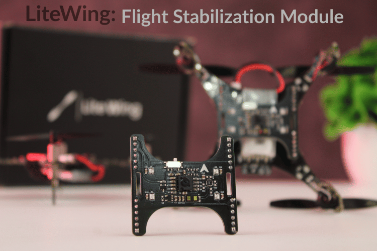
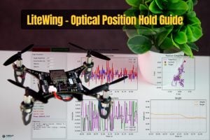
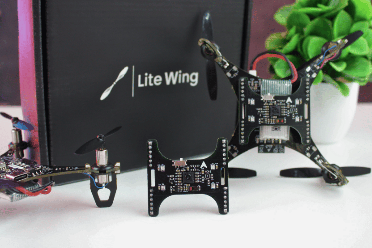
The LiteWing Drone Positioning Module is a plug-and-play optical flow and ToF-based stabilization add-on designed for indoor and GPS-denied flight. Featuring the PMW3901 optical flow sensor for precise X/Y position tracking and the VL53L1X Time-of-Flight sensor for accurate height measurement, this module enables stable height hold and position hold performance. Ideal for DIY drones, autonomous flight experiments, and educational robotics projects.
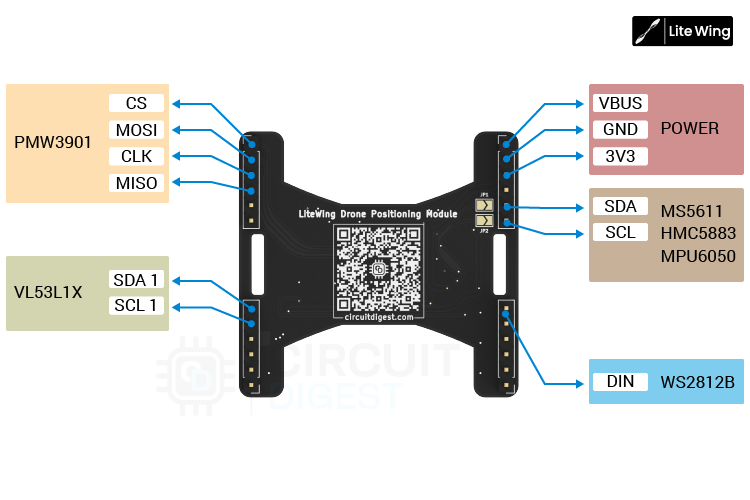
This module transforms your ESP32 LiteWing Drone into a fully-equipped autonomous flight platform by adding critical sensor capabilities: precision ToF height measurement, optical motion tracking, and visual status feedback. All connected through a 24-pin connector, eliminating complex wiring while maintaining robust electrical connections suitable for flight operations.
This add-on module is completely compatible with the LiteWing Drones and consists of the VL53L1x ToF sensor and PMW3901MB optical flow sensor for height hold and position hold, respectively. Apart from this, the module also has 4 Neopixel LEDs that can be programmed to indicate flight status or for visual appeal.
Important: By default, only the ToF sensor, Optical Flow sensor, and Neopixel LEDs will be soldered on the module. The brometric sensor and magnetometer footprint is added only for users who wish to build more using the same board. By default these two sensors will not be populated. The colour of the PCB might also be in black or green color depending on the time of purchase, but features and working will reamin the same.
Specifications
| Specification | Details |
| Dimensions | 46mm × 44mm (L × W) |
| Weight | ~8 grams (including components) |
| Connector | 24-pin male header pins (2×12 configuration) |
| Power Requirements | 3.3V from drone (via connector) |
| Communication | I²C (Height sensor), SPI (Optical flow), Single Wire (Neopixel) |
| Mounting | Bottom-side of LiteWing drone via expansion headers |
Quick Start Tutorials for Positioning Module with LiteWing Drone
Hardware Overview
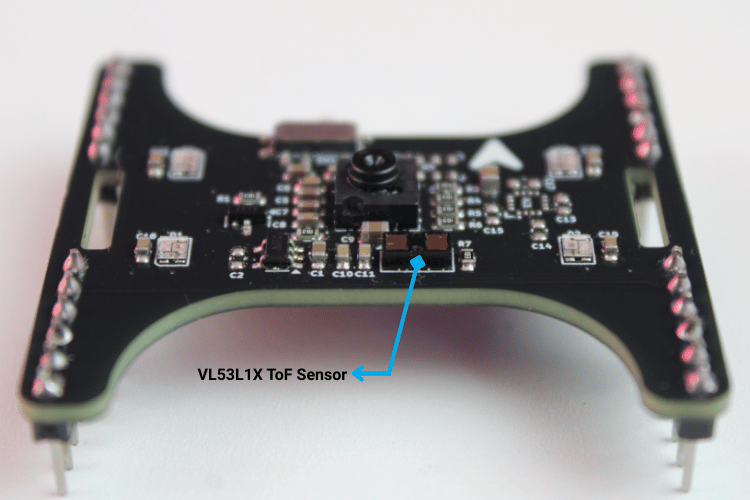
On the bottom side of the PCB, just above the Semicon Lab logo, we placed the VL53L1X Time-of-Flight distance sensor. This downward-facing ToF device provides precise ground height measurements, making it ideal for height hold and low-altitude autonomous flight.
At the center of the module, you’ll find the PMW3901 optical flow sensor. This positioning ensures an unobstructed view of the ground surface, allowing reliable X/Y motion tracking for horizontal position hold and drift correction.
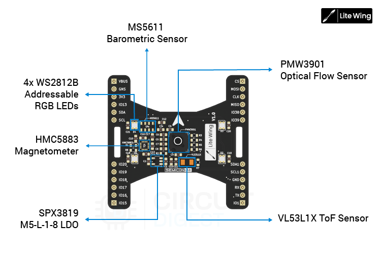
Toward the bottom-left area of the board, we integrated a dedicated SPX3819M5-L-1-8 LDO regulator, which supplies the required low-noise power rail for the optical flow sensor, ensuring stable operation and consistent motion data.
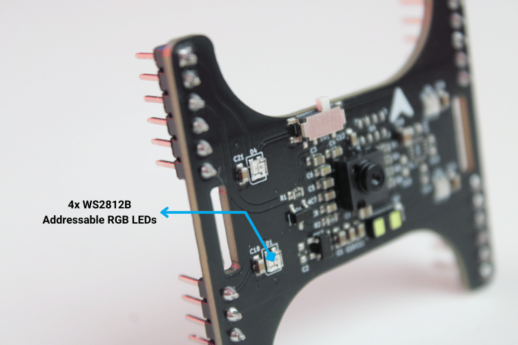
For visual feedback and debugging, four WS2812B addressable RGB LEDs are placed at each corner of the module. This symmetric placement makes status indications clearly visible from any angle, while still using only a single data line for control. These LEDs are used for boot indication, mode status, calibration feedback, and general diagnostics.
On the left side of the PCB, we’ve also provided unpopulated footprints for two optional sensors: MS5611 barometric pressure sensor (for altitude estimation), HMC5883L magnetometer (for heading reference) At present, firmware support for these two devices is still under development. However, advanced users are welcome to populate these pads according to the provided schematics and modify the LiteWing source code to suit their requirements.
All other onboard sensors, including the VL53L1X, PMW3901, and WS2812B LEDs, are natively supported on LiteWing after the firmware update, which we’ll cover in the following sections.
VL53L1X Time-of-Flight Distance Sensor
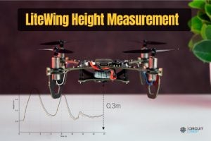
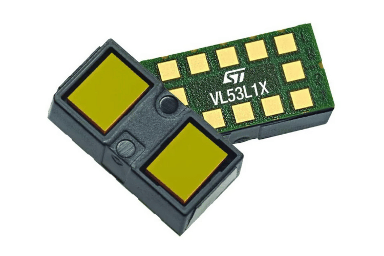
For height measurement, the shield uses the VL53L1X, a compact Time-of-Flight (ToF) module from STMicroelectronics. It operates using a 940 nm Class-1 laser emitter and a SPAD array to measure the return time of reflected photons. This approach provides consistent short-range height data and is less affected by airflow noise compared to ultrasonic sensors. The onboard microcontroller handles ranging calculations and outputs distance values directly over I²C, reducing processing load on the main flight controller.
Specifications
| Parameter | Value |
| Ranging Distance | Up to 4 m |
| Measurement Rate | Up to 50 Hz |
| Emitter | 940 nm IR (Class-1) |
| Receiver | SPAD array with integrated optics |
| Interface | I²C |
| Notes | Onboard firmware handles all ranging computations |
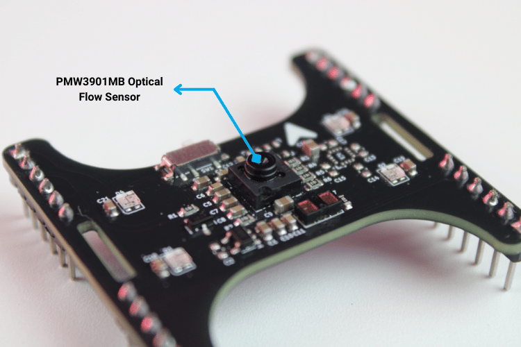
PMW3901MB Optical Flow Sensor
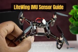
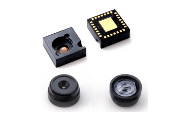
Horizontal drift correction is handled by the PMW3901MB-TXQT, an optical flow sensor designed for motion tracking in aerial platforms. The sensor continuously captures low-resolution surface images and computes X/Y displacement between frames. It is suitable for indoor and GPS-denied environments where vision-based reference is required. And it allows stable operation during slow and low-altitude flight.
Specifications
| Parameter | Value |
| Working Range | 80 mm to 2m |
| Power Consumption | ~9 mA (run mode) |
| Output Data | 16-bit X and Y motion registers |
| Optics | Far-field lens, no focus adjustment needed |
| Interface | SPI |
WS2812B Addressable RGB LEDs (4-LED Array)
The module includes a small array of four WS2812B RGB LEDs used primarily for status indication, mode alerts, and general debugging feedback. Each LED integrates its own controller, allowing all LEDs to be driven over a single data line. This keeps wiring minimal and simplifies firmware control, especially during system diagnostics and calibration.
Specifications
| Parameter | Value |
| LED Count | 4 |
| Package | 2020 RGB + controller |
| Typical Current | ~12 mA per color channel |
| Control | Single-wire serial protocol |
| Notes | Individually addressable for multi-color status patterns |
Sensors Overview
SPI Interface – Optical Flow Sensor (PMW3901)
The PMW3901 optical flow sensor uses a dedicated SPI interface for high-speed motion data transfer. This SPI bus is reserved exclusively for the optical flow sensor, allowing continuous and deterministic access to X and Y displacement data without interference from other peripherals.
| Signal | Function | ESP32-S3 GPIO |
| MISO | SPI data from PMW3901 | GPIO37 |
| CLK | SPI clock | GPIO36 |
| MOSI | SPI data to PMW3901 | GPIO35 |
| CS | Chip select | GPIO42 |
I²C1 Interface – Time-of-Flight Sensor
The VL53L1X Time-of-Flight distance sensor is connected to a separate I²C bus (I²C1). Using a dedicated I²C channel for height measurement isolates ranging traffic from other I²C devices and improves measurement stability, particularly during fast control loop updates in altitude-hold modes.
| Signal | Function | ESP32-S3 GPIO |
| SCL1 | I²C clock | GPIO41 |
| SDA1 | I²C data | GPIO40 |
I²C0 Interface – IMU, Barometer, and Magnetometer
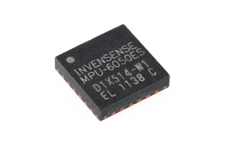
The primary I²C bus (I²C0) is shared between the LiteWing drone’s onboard IMU and the optional expansion sensors provided on the Flight Positioning Module. This shared bus connects the onboard MPU6050 IMU along with the unpopulated footprints for the MS5611 barometric pressure sensor and HMC5883L magnetometer.
Important: The firmware support for the barometer and magnetometer is still under development; the electrical connections are already in place for users who wish to populate the components and extend functionality through custom firmware. By default, the MS5611 and HMC5883L will not be soldered with the LiteWing drone position module.
| Signal | Function | ESP32-S3 GPIO |
| SCL | I²C clock | GPIO10 |
| SDA | I²C data | GPIO11 |
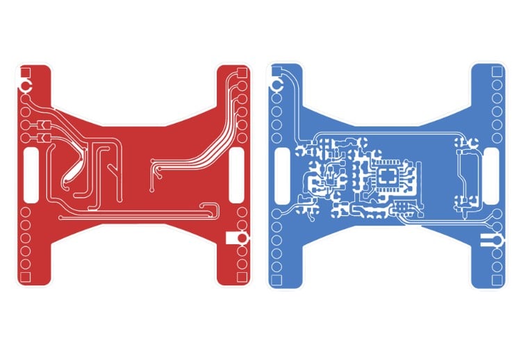
PCB Design & Layout
The hardware design for the LiteWing Drone positioning module, along with the schematics is made open-source for people to try and experiment. All designs are under a CC license; you are free to build, modify, and share.
| Resource | Description | Link |
| Circuit Diagrams | Circuit Diagrams | GitHub Repository |
| Gerber Files | Gerber Files are currently not made open | – |
| Firmware Binary Source | Firmware Binary Source | GitHub Repository |
Interactive BOM
Circuit Diagram
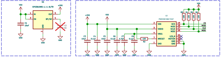
UPMW3901 Optical Flow Sensor + 1.8 V LDO Supply
The PMW3901 optical flow sensor operates internally at 1.8 V, so the module includes a dedicated low-dropout regulator to derive this rail from the drone’s main 3.3 V supply. A compact SPX3819M5-L-1-8 LDO is used to generate the +1.8 V domain, ensuring a clean and stable supply for the image sensor core.
Multiple ceramic capacitors (10 µF, 4.7 µF, 0.1 µF) are placed close to the regulator output and the PMW3901 power pins. These provide local energy storage and high-frequency noise suppression.
The PMW3901 communicates with the LiteWing controller over SPI. The MISO, MOSI, CLK, and CS lines are routed directly from the expansion connector to the sensor. 10 kΩ pull-up resistors are used on the SPI signal lines. These pull-ups ensure that MISO, MOSI, CLK, and CS do not float during power-up or reset conditions, keeping the optical flow sensor in a known idle state until the LiteWing firmware takes control. This helps prevent unintended SPI activity and improves startup reliability.A 10K pull-up resistor is provided on the reset line to ensure the sensor powers up in a known state. Additional decoupling capacitors are tied to the internal VREG pin of the PMW3901, following the reference design to stabilize the internal analog supply.
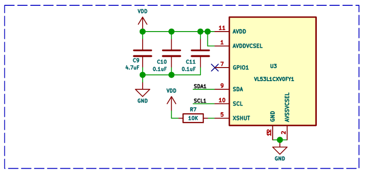
VL53L1X Time-of-Flight Height Sensor
The VL53L1X ToF sensor is powered directly from the module’s 3.3 V rail. Local bypass capacitors (4.7 µF and 0.1 µF) are placed close to the AVDD pins to reduce supply ripple and ensure stable ranging performance.
Communication with the LiteWing controller happens over the dedicated I²C1 bus. The SDA and SCL lines are routed straight to the expansion connector, keeping this height sensor electrically isolated from the main IMU I²C bus.
The XSHUT pin is pulled high through a 10 kΩ resistor, allowing the sensor to power up automatically when 3.3 V is applied. This also leaves room for future firmware control of hardware shutdown if needed. The GPIO1 pin is left unused in the current design, as all ranging operations are handled internally by the VL53L1X.
All ground pins are tied directly to the common ground plane beneath the sensor, minimizing impedance and helping maintain consistent ToF measurements during rapid throttle changes.
WS2812B Addressable RGB LED Chain
The module uses four WS2812B addressable RGB LEDs arranged in a daisy-chain configuration. Each LED receives data from the previous device’s DOUT pin, allowing all four LEDs to be controlled from a single GPIO line on the LiteWing controller.
The LEDs are powered directly from the VBUS rail, with a dedicated 1 µF capacitor placed next to each LED. These capacitors supply instantaneous current during color changes and prevent voltage dips that could corrupt the serial data stream.
Data enters the first LED through the DIN pin, propagates through the chain, and terminates at the final LED. The last DOUT is left unconnected, as no additional devices follow.
Update LiteWing Drone Firmware for Compatibility
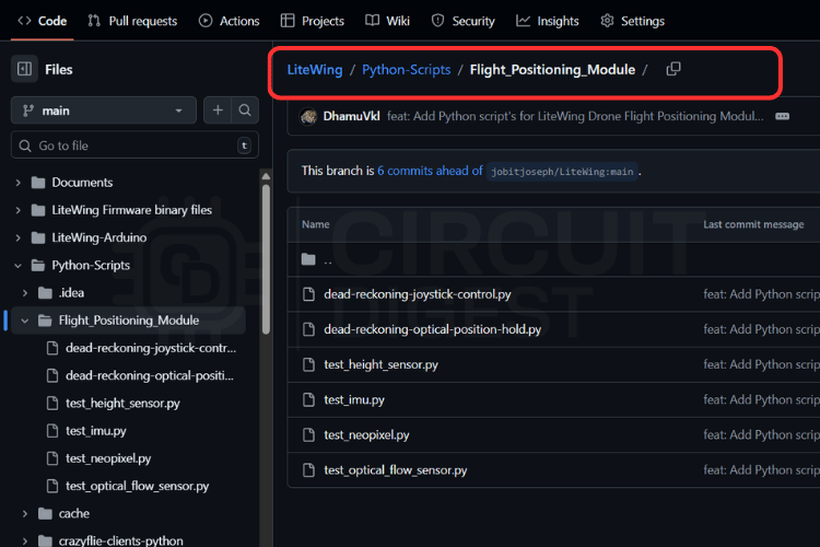
STEP1: Download the latest firmware from GitHub
To enable the LiteWing Drone Flight Positioning Module, you must update the firmware of the drone. The required firmware binaries are maintained in the LiteWing GitHub repository under the folder “LiteWing Firmware binary files / LiteWing Flight Positioning Module Firmware”.
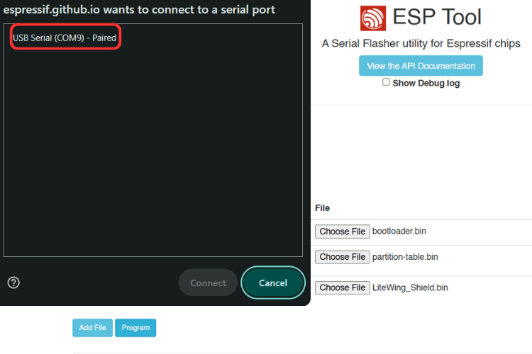
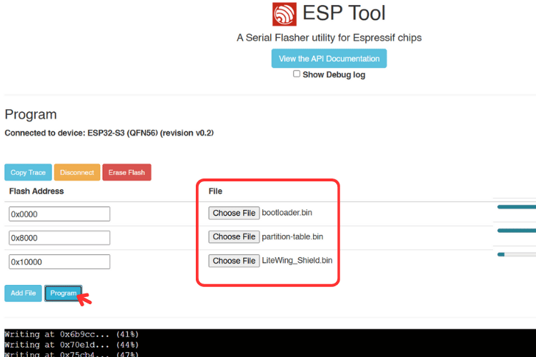
STEP2: Flashing with ESPtool.js (Web-based, Cross-platform)
For anyone who prefers a browser-based method, ESPtool.js provides an alternative flashing workflow.
| Step | Action |
| 1 | Open the ESPtool.js website in a supported browser |
| 2 | Connect the LiteWing via USB Type-C |
| 3 | Click Connect |
| 4 | Select the USB serial device when prompted |
| 5 | Add the firmware binaries with their corresponding addresses |
| 6 | Click Program to begin flashing |
Note on Auto-Reset Behavior: In some browsers, especially Chrome-based ones, the ESP32-S3 may not automatically reset after flashing. If this occurs, press the Reset button on the LiteWing board to start the new firmware.
STEP3: Firmware Binary Files and Flash Addresses
When flashing the ESP32-S3 using binary images, ensure the files are written to the correct memory offsets. Incorrect addresses will prevent the board from booting. If you are stuck with something, check out the detailed guide on how to flash firmware on the LiteWing Drone.
Flash Address Mapping
| Binary File | Flash Address | Purpose |
| bootloader.bin | 0x0000 | ESP32-S3 bootloader |
| partition-table.bin | 0x8000 | Storage layout definitions |
| LiteWing_Shield.bin | 0x10000 | Flight controller application with Shield support |
How to use the Flight Positioning Module
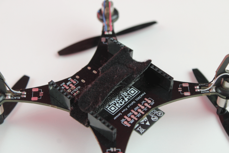
The LiteWing drone includes a pair of 2×12 (24-pin) expansion connectors on the underside of the main board. These serve as the primary interface for add-on modules. Before installing the Flight Positioning Module, ensure the drone is powered off completely. Connecting or disconnecting hardware while the processor or power stages are active can lead to unexpected behavior or damage.
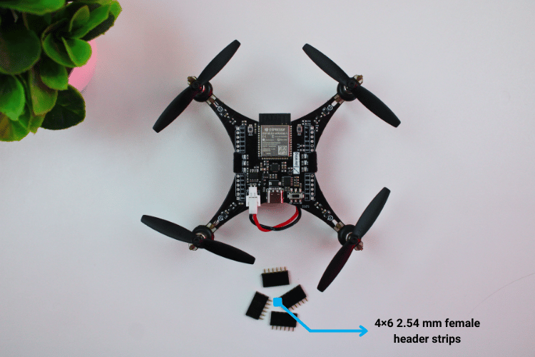
If your LiteWing board does not have female headers pins soldered to the expansion pads, this step must be done first. The shield uses matching male headers pins, so the drone requires 24-pin female headers pins soldered in place. Standard 2×12 2.54 mm female header strips are compatible. Once soldered, visually check alignment and ensure the pins sit perpendicular to the PCB to allow the shield to mate properly.
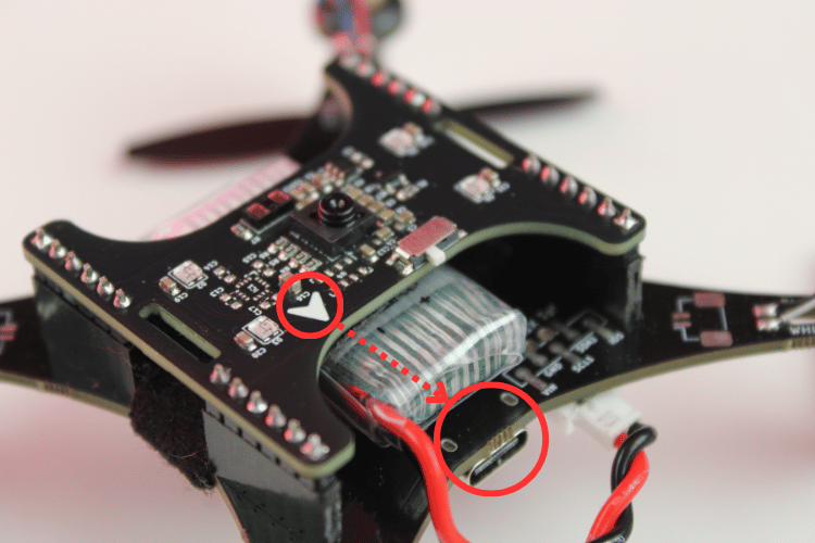
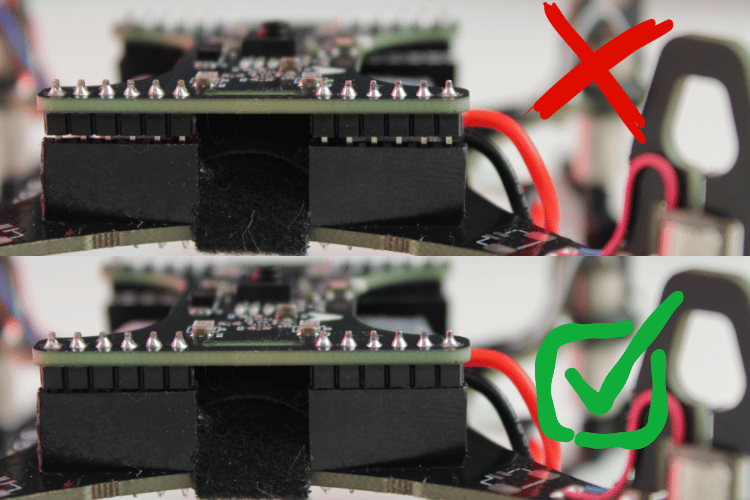
The shield includes a printed orientation arrow on the silkscreen. This mark is used to ensure correct alignment when connecting the module. When installing the shield, the arrow should point toward the USB Type-C port on the drone. This orientation ensures that power, ground, I²C, SPI, and auxiliary pins align correctly with the LiteWing pinout.
To mount the shield, position it above the drone so the male pins line up with the female expansion headers. Insert the shield by applying even downward pressure across both connectors. The board should slide in smoothly without forcing. Once seated, the shield should sit flush against the female headers with no visible gaps. Check that none of the pins are misaligned or bending outward during insertion.
After confirming the mechanical connection, power on the drone. During startup, the system should boot without faults, and the four WS2812B LEDs on the shield will briefly flash to indicate that the module has powered up correctly. If the drone fails to start power off immediately and recheck the connector alignment.
You are all set to start flying and programming. Just make sure you have installed the latest firmware on your drone and fly using the LiteWing mobile app in height hold mode
Check out the quick start tutorials on top of this page, where we focus on communicating with each sensor to confirm operation, reading distance values from the VL53L1X, retrieving motion data from the PMW3901MB, and driving the WS2812B LED array for status indication. These capabilities will then be used to support autonomous flight operations, including position hold, joystick-assisted control with position hold, and maneuvering controls.
Where to Buy?
LiteWing project is designed and maintained by CircuitDigest under the SemiconLab initiative. You can buy LiteWing Drones from our distributors listed below:

Have any Questions?
Start a Discussion on:
I would like to purchase 2 LiteWing Flight Positioning Modules and 2 LiteWing – ESP32 based Programmable Drone.
I live in the USA:
I can pay with PayPal.
I would like to purchase one LiteWing Flight Positioning Module and one LiteWing Drone.
I live in the United States and I can pay with PayPal.
Hi Robert, US customers can buy from tindie (https://www.tindie.com/products/semicon_lab/litewing-drone-positioning-module/)
I bought a drone before and plan to buy more, but the LiteWing Drone Positioning Module is not yet available on the Tidie site.
Please let me know when it shows up.
Thanks,
Rob Parenton
How can I get the open source for the drone positioning module? I notice it is not on your GitHub site.
I would like to purchase LiteWing Flight Positioning Modules since I already got LiteWing ESP32 Drone on Tindie.
Could you tell me how? I leave in Naples, Italy.
Thanks
Yes, you can buy from tindie (https://www.tindie.com/products/semicon_lab/litewing-drone-positioning-module/) and use it with your existing LiteWing Drone. Just make sure you have updated the firmware