
In today’s automation world stepper motor and servo motor are two most commonly used motors in embedded systems. Both are used in various automation machines like robotic arms, CNC machine, cameras etc. In this tutorial we will see how to interface Stepper Motor with ARM7-LPC2148 and how to control speed of it. If you are new to ARM7 then start by learning about ARM7-LPC2148 and its programming tools.
Stepper Motor
Stepper motor is brushless DC motor, which can be rotated in small angles, these angles are called steps. We can rotate stepper motor step by step by giving digital pulses to its pins. Stepper motors are inexpensive and have rugged design. Speed of the motor can be controlled by changing frequency of digital pulses.
There are two types of stepper motors available based on the type of stator winding: UNIPOLAR and BIPOLAR. Here we are using UNIPOLAR stepper motor which is the most commonly used stepper motor. To rotate the stepper motor we need to energise the coils of the stepper motor in a sequence. Based on the rotational operation they are classified into two modes:
- Full Step Mode: (4-Step Sequence)
- One-Phase On Stepping (WAVE STEPPING)
- Two-Phase On Stepping
- Half Step Mode (8-Step Sequence)
To know more about stepper motor and its operation, follow the link.
Rotating a Stepper Motor WITH ARM7-LPC2148

Here we will use FULL STEP: ONE PHASE ON or WAVE STEPPING mode to rotate the Stepper Motor with ARM7-LPC2148
In this method we will energise only one coil (one pin of LPC2148) at a time. That is if the first coil A is energised for a small time, shaft will change its position and then coil B is energised for the same time and shaft will again change its position. Same like this, coil C and then coil D is energised to move shaft further. This makes stepper motor’s shaft to rotate in a step by step manner by energising one coil at a time.
By this method we rotate the shaft step by step by energizing coil in a sequence. This is called four step sequences as it takes four steps.
You can rotate stepper Motor using HALF STEP method (8-Sequence method) according to the values given below.
|
Step |
Coil A |
Coil B |
Coil C |
Coil D |
|
1 |
1 |
0 |
0 |
0 |
|
2 |
1 |
1 |
0 |
0 |
|
3 |
0 |
1 |
0 |
0 |
|
4 |
0 |
1 |
1 |
0 |
|
5 |
0 |
0 |
1 |
1 |
|
6 |
0 |
0 |
0 |
1 |
|
7 |
1 |
0 |
0 |
1 |
|
8 |
1 |
0 |
0 |
0 |
Components Required
Hardware:
- ARM7-LPC2148
- ULN2003 Motor Driver IC
- LED – 4
- STEPPER MOTOR (28BYJ-48)
- BREADBOARD
- CONNECTING WIRES
Software:
- Keil uVision5
- Flasic Magic Tool
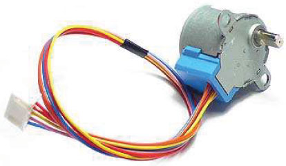
Stepper Motor (28BYJ-48)
28BYJ-48 stepper motor is already shown in the picture above. It is a Unipolar Stepper motor which requires 5V supply. The motor has a 4 coil unipolar arrangement and each coil is rated for +5V hence it is relatively easy to control with any microcontrollers like Arduino, Raspberry Pi, STM32, ARM etc.
But we need a Motor Drive IC like ULN2003 to drive it, because stepper motors consume high current and it may damage microcontrollers.
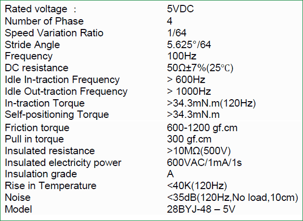
The specifications of 28BYJ-48 are provided in datasheet below:
Also check interfacing with Stepper Motor with other Microcontrollers:
- Interfacing Stepper Motor with Arduino Uno
- Stepper Motor Control with Raspberry Pi
- Stepper Motor Interfacing with 8051 Microcontroller
- Interfacing Stepper Motor with PIC Microcontroller
- Interfacing Stepper Motor with MSP430G2
Stepper motor can also be controlled without any Microcontroller, see this Stepper Motor Driver Circuit.
ULN2003 Stepper Motor Driver
Most stepper motors will operate only with the help of a driver module. This is because the controller module (In our case LPC2148) will not be able to provide enough current from its I/O pins for the motor to operate. So we will use an external module like ULN2003 module as stepper motor driver.
In this project, we will use ULN2003 motor driver IC. Pin diagram of IC is given below:
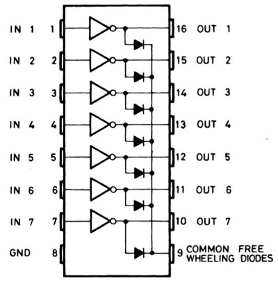
Pins (IN1 to IN7) are input pins for connecting microcontroller output and OUT1 to OUT7 are corresponding output pins for connecting stepper motors input. COM is given Positive source voltage required for output devices and for external power input source.
Circuit Diagram
Circuit diagram for interfacing Stepper Motor with ARM-7 LPC2148 is given below

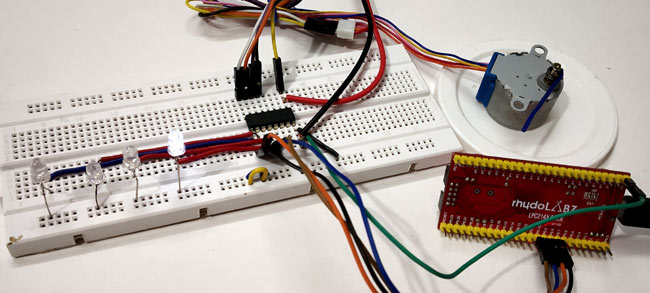
ARM7-LPC2148 with ULN2003 Motor Driver IC
GPIO Pins of LPC2148 (P0.7 to P0.10) are considered as output pins that are connected with input pins (IN1-IN4) of the ULN2003 IC.
|
LPC2148 Pins |
PINS OF ULN2003 IC |
|
P0.7 |
IN1 |
|
P0.8 |
IN2 |
|
P0.9 |
IN3 |
|
P.10 |
IN4 |
|
5V |
COM |
|
GND |
GND |
Connections of ULN2003 IC with Stepper Motor (28BYJ-48)
The output pins (OUT1-OUT4) of ULN2003 IC are connected to the stepper motors pins (Blue, Pink, Yellow, and Orange).
|
ULN2003 IC PINS |
PINS OF STEPPER MOTOR |
|
OUT1 |
BLUE |
|
OUT2 |
PINK |
|
OUT3 |
YELLOW |
|
OUT4 |
ORANGE |
|
COM |
RED (+5V) |
LEDs with IN1 to IN4 of ULN2003
Four LED’s (LED1, LED2, LED4, LED 4) anode pins are connected with the pins IN1, IN2, IN3, and IN4 of ULN2003 respectively and cathode of the LEDs are connected to GND which is to indicate the pulses from the LPC2148. We can note the pattern of the pulses provided. Pattern is shown in the demonstration video attached at the end.
Programming ARM7-LPC2148 for Stepper Motor
To Program ARM7-LPC2148 we need keil uVision & Flash Magic tool. We are using USB Cable to program ARM7 Stick via micro USB port. We write code using Keil and create a hex file and then the HEX file is flashed to ARM7 stick using Flash Magic. To know more about installing keil uVision and Flash Magic and how to use them follow the link Getting Started With ARM7 LPC2148 Microcontroller and Program it using Keil uVision.
The complete code for controlling Stepper Motor with ARM 7 is given at the end of this tutorial, here we are explaining few parts of it.
1. For using the FULL STEP-ONE PHASE ON method we need to include below command. So we use the following line in the program
unsigned char clockwise[4] = {0x1,0x2,0x4,0x8};     //Commands for clockwise rotation
unsigned char anticlockwise[4] = {0x8,0x4,0x2,0x1}; //Commands for anticlockwise rotation
2. The following lines are used to initialise the PORT0 pins as output and set them to LOW
PINSEL0 = 0x00000000; //Setting PORT0 pins
IO0DIR |= 0x00000780; //Setting pins P0.7, P0.8, P0.9, P0.10 as OUTPUT
IO0CLR = 0x00000780;  //Setting P0.7, P0.8, P0.9, P0.10 pins OUTPUT as LOW
3. Set the PORT pins (P0.7 to P0.10) HIGH according Clockwise commands by using this for loop with delay
for (int j=0; j<no_of_steps;j++)
                {
                for(int i=0; i<4;i++)
                {
                IOPIN0 =clockwise[i]<<7;  // Setting the pin value HIGH one by one after shifting bit to left
                delay(0x10000);           //Change this value to change the speed of rotation
                }
                }
Same for Anti-clock Wise
for (int z=0;z<no_of_steps;z++)
                {
                for(int i=0; i<4;i++)
                {
                IOPIN0 =anticlockwise[i]<<7;
                delay(0x10000);            //Change this value to change the speed of rotation
                }
                }
4. Change the delay time to change the speed of rotation of stepper motor
delay(0x10000);            //Change this value to change the speed of rotation
(0x10000)-Full speed
(0x50000)-Gets slow
(0x90000)-Gets slow than previous. So by increasing delay we low the speed of rotation.
5. Number of steps for one complete rotation can be changed with the below code
int no_of_steps = 550; //Change this value for required number of steps rotation (550 gives one complete rotation)
For my stepper motor, I got 550 steps for complete rotation and 225 for half rotation. So change it according to your requirements.
6. This function is used to create delay time.
void delay(unsigned int value)       //Function to generate delay
{
    unsigned int z;
    for(z=0;z<value;z++);
}
Complete code with demonstration Video is given below.
