

Home automation systems are increasingly gaining popularity day by day, and nowadays it's become easy to turn on & off certain appliances by using some simple control mechanism like a relay or a switch, we have previously built many Arduino based Home Automation Projects using relays. But there are many home appliances that require control of this AC power rather than just turning on or off. Now, enter the world of AC phase angle control, it's a simple technique through which you can control the AC phase angle. This means you can control the speed of your ceiling fan or any other AC fan or even you can control the intensity of a LED or incandescent light bulb.
Though it sounds simple, the process of actually implementing it is very difficult, so in this article, we are going to build a simple AC phase angle control circuit with the help of a 555 timer, and in the end, we will use an Arduino to generate a simple PWM signal to control the intensity of an incandescent light bulb. As you can now clearly imagine, with this circuit, you can build a simple home automation system where you can control the fan and Ac light dimmers with a single Arduino.
What is an AC Phase Angle Control and How does it Work?
AC phase angle control is a method through which we can control or chop an AC sine wave. The firing angle of the switching device is varied following a zero-crossing detection, resulting in an average voltage output that changes proportionally with the modified sine wave, the image below describes more.
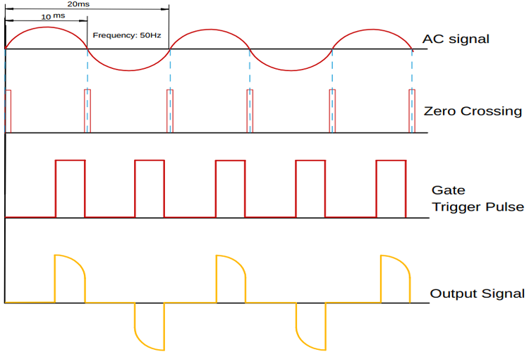
As you can see, first we have our AC input signal. Next, we have the zero-crossing signal, which generates an interrupt every 10ms. Next, we have the gate trigger signal, once we get a triggering signal, we wait for a certain period before giving the trigger pulse, the more we wait, the more we can reduce the average voltage and vice versa. We will discuss more of the topic later in the article.
Challenges in Phase Angle Control
Before we take a look at the schematic and all the material requirements, let's talk about some problems which are associated with this kind of circuit and how our circuit solves those.
Our objective here is to control the phase angle of an AC sine wave with the help of a microcontroller, for any kind of home automation application. If we look at the image below, you can see that in yellow, we have our sine wave, and in green, we have our zero-crossing signal.
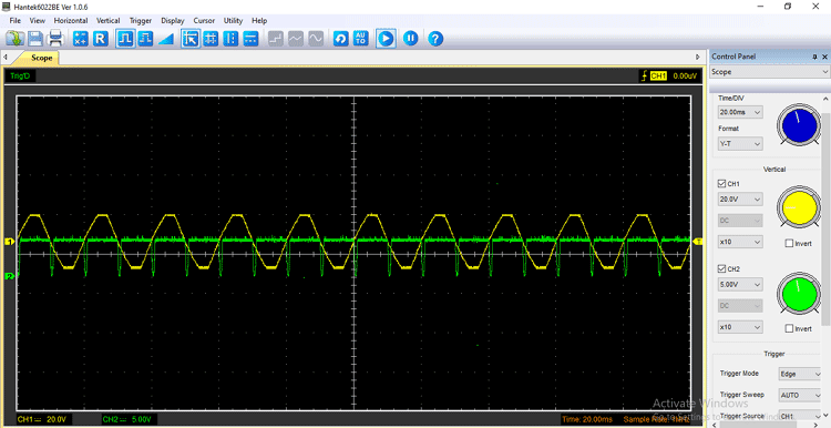
You can see that the zero-crossing signal comes in every 10ms as we are working with a 50Hz sine wave. In a microcontroller, it generates an interrupt every 10ms. if we were to put any other code besides that, the other code may not work due to interruption. As we know the line frequency hear in India is 50Hz, so we are working with a 50Hz sine wave, and in order to control the mains AC, we need to turn on and off the TRIAC in a certain time frame. To do that, the microcontroller-based phase angle control circuit uses the zero-crossing signal as an interrupt, but the problem with this method is that you cannot run any other code besides the pace angle control code, because in a way it will break the loop cycle and one of those codes will not work.
Let me clarify with an example, suppose you have to do a project where you need to control the brightness of the incandescent light bulb, also you need to measure the temperature at the same time. To control the brightness of an incandescent light bulb, you need a phase angle control circuit, also you need to read the temperature data along with it, if this is the scenario, your circuit will not work properly because the DHT22 sensor takes some time to give its output data. In this period of time, the phase angle control circuit will stop working, that is if you have configured it in a polling mode, but if you configured the zero-crossing signal in interrupt mode, you will never be able to read the DHT data because the CRC check will fail.
To solve this problem, you can use a different microcontroller for different phase angle control circuit but it will increase the BOM cost, another solution is to use our circuit which is made up of generic components like the 555 timer and also costs less.
Material Required for AC Phase Angle Control Circuit
The image below shows the materials used to build the circuit, as this is made with very generic components, you should be able to find all of the listed material in your local hobby store.
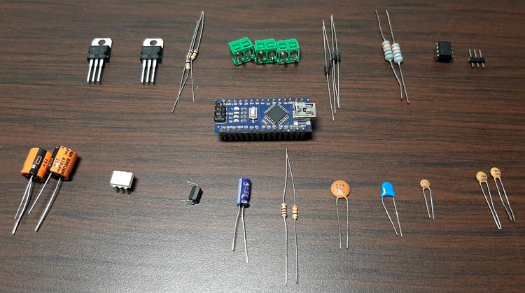
I have also listed the components in a table below with type and quantity, since it’s a demonstration project, I am using a single channel to do so. But the circuit can be easily scaled up as per requirement.
|
Sl.No |
Parts |
Type |
Quantity |
|
1 |
Screw Terminal 5.04mm |
Connector |
3 |
|
2 |
Male Header 2.54mm |
Connector |
1X2 |
|
3 |
56K,1W |
Resistor |
2 |
|
4 |
1N4007 |
Diode |
4 |
|
5 |
0.1uF,25V |
Capacitor |
2 |
|
6 |
100uF,25V |
Capacitor |
2 |
|
7 |
LM7805 |
Voltage Regulator |
1 |
|
8 |
1K |
Resistor |
1 |
|
9 |
470R |
Resistor |
2 |
|
10 |
47R |
Resistor |
2 |
|
11 |
82K |
Resistor |
1 |
|
12 |
10K |
Resistor |
1 |
|
13 |
PC817 |
Optocoupler |
1 |
|
14 |
NE7555 |
IC |
1 |
|
12 |
MOC3021 |
OptoTriac Drive |
1 |
|
13 |
IRF9540 |
MOSFET |
1 |
|
14 |
3.3uF |
Capacitor |
1 |
|
15 |
Connecting Wires |
Wires |
5 |
|
16 |
0.1uF ,1KV |
Capacitor |
1 |
|
17 |
Arduino Nano (For Test) |
Microcontroller |
1 |
AC Phase Angle Control Circuit Diagram
The schematic for the AC phase angle control circuit is shown below, this circuit is very simple and uses generic components to achieve phase angle control.

AC Phase Angle Control Circuit – Working
This circuit is made up of very carefully designed components, I will go through each one and explain each block.
Zero-Crossing Detection Circuit:
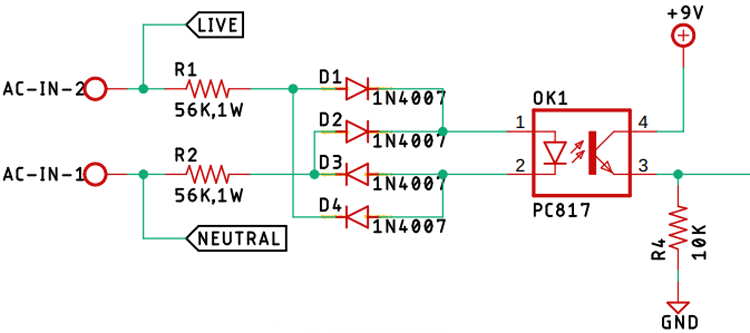
First, in our list is the zero-crossing detection circuit is made with two 56K, 1W resistors in conjunction with four 1n4007 diodes and a PC817 optocoupler. And this circuit is responsible for providing the zero-crossing signal to the 555 timer IC. Also, we have taped-off the phase and the neutral signal to further use it in the TRIAC section.
LM7809 Voltage Regulator:
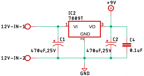
The 7809-voltage regulator is used to power the circuit, the circuit is responsible for providing power to the whole circuit. Additionally, we have used two 470uF capacitors and a 0.1uF capacitor as a decoupling capacitor for the LM7809 IC.
Control Circuit with NE555 Timer:
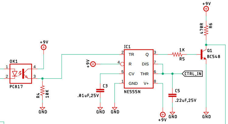
The above image shows the 555 timer control circuit, the 555 is configured in a monostable configuration, so when a trigger signal from the zero-crossing detection circuit hits the trigger, the 555 timer starts to charge the capacitor with the help of a resistor (in general), but our circuit has a MOSFET in place of a resistor, and by controlling the gate of the MOSFET, we control the current going to the capacitor, that's why we control the charging time hence we control the output of the 555 timers. In many projects, we have utilized the 555 timer IC in order to make our project, if you want to know more about this topic, you can check out all other projects.
TRIAC and the TRIAC-Driver Circuit:
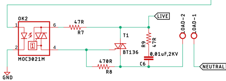
The TRIAC is acting as the main switch which actually turns on and off, thus controls the output of the AC signal. Driving the TRIAC is the MOC3021 optotriac drive, it doesn't only drive the TRIAC, but it also provides optical isolation, the 0.01uF 2KV high voltage capacitor, and the 47R resistor forms a snubber circuit, which protects our circuit from high voltage spikes which occur when it's connected to an inductive load, the non-sinusoidal nature of the switched AC signal is responsible for the spikes. Also, it's responsible for power factor issues, but that is a topic for another article. Also, in various articles, we have utilized the TRIAC as our preferred device, you can check those out if that peeks your interest.
Lowpass-Filter and the P-Channel MOSFET (Acting as the Resistor in the Circuit):
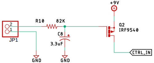
The 82K resistor and the 3.3uF capacitor forms the low pass filter which is responsible for smoothing out the high-frequency PWM signal generated by the Arduino. As previously mentioned, the P-Channel MOSFET acts as the variable resistor, which controls the charging time of the capacitor. Controlling it is the PWM signal which is smoothed out by the low-pass filter. In the previous article, we have cleared out the concept of lowpass filters, you can check out the article on active low pass filter or passive low pass filter if you want to know more about the topic.
PCB Design for the AC Phase Angle Control Circuit
The PCB for our Phase angle Control circuit is designed in a single-sided board. I have used Eagle to design my PCB but you can use any Design software of your choice. The 2D image of my board design is shown below.
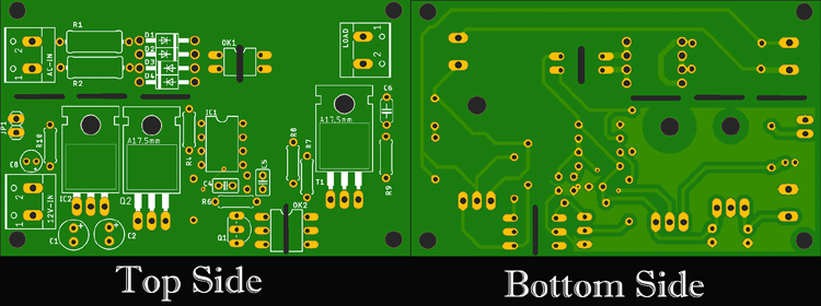
Sufficient ground filling is used to make proper ground connections among all the components. The 12V DC input and the 220 Volt AC input is populated at the left-hand side, the output is located on the right-hand side of the PCB. The complete design file for Eagle along with the Gerber can be downloaded from the link below.
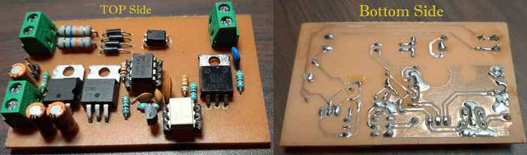
Handmade PCB:
For convenience, I made my handmade version of the PCB and it's shown below.
Arduino Code for AC Phase Angle Control
A simple PWM generation code is used to make the circuit work, the code and its explanation is given below. You can also find the complete code at the bottom of this page. First, we declare all the necessary variable,
const int analogInPin = A0;  // Analog input pin that the potentiometer is attached to
const int analogOutPin = 9; // Analog output pin that the LED is attached to
int sensorValue = 0;  // value read from the pot
int outputValue = 0; // value output to the PWM (analog out)
The variables are to declare the Analog pin, the analogOut pin, and the other variables are to store, convert, and print the mapped value. Next in the setup() section, we initial the UART with 9600 baud so that we could monitor the output and that’s how we can find out which PWM range was able to totally control the output of the circuit.
void setup() {
  // initialize serial communications at 9600 bps:
  Serial.begin(9600);
}
Next, in the loop() section, we read the analog pin A0 and store the value to sensor value variable, next we map the sensor value to 0 -255 as because the PWM timer of the atmega is only 8-bits, next we set the PWM signal with an analogWrite() function of the Arduino. and finally, we print the values to the serial monitor window to find out the range of the control signal, if you are following this tutorial, the video at the end will give you a clearer idea on the topic.
sensorValue = analogRead(analogInPin);// read the analog in value:
outputValue = map(sensorValue, 0, 1023, 0, 255);  // map it to the range of the analog out:
analogWrite(analogOutPin, outputValue); // change the analog out value:
Serial.print("sensor = "); // print the results to the Serial Monitor:
Serial.print(sensorValue);
Serial.print("\t output = ");
Serial.println(outputValue);
Testing the AC Phase Angle Control Circuit
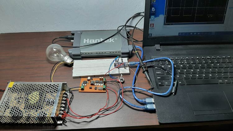
The above image shows the test setup of the circuit. The 12V supply is provided by a 12V SMPS circuit, the load is a light bulb in our case, it can be easily replaced \with an inductive load like a fan. Also as you can see that I have attached a potentiometer in order to control the brightness of the lamp but it can be replaced with any other form of controller, if you zoom in on the image, you can see that the pot is connected to the A0 pin of the Arduino and the PWM signal is coming from the pin9 of the Arduino.
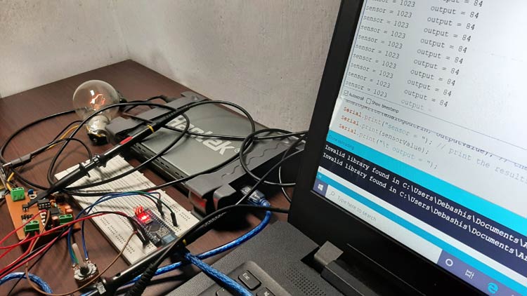
As you can see in the above picture, the output value is 84 and the brightness of the incandescent light bulb is very low,
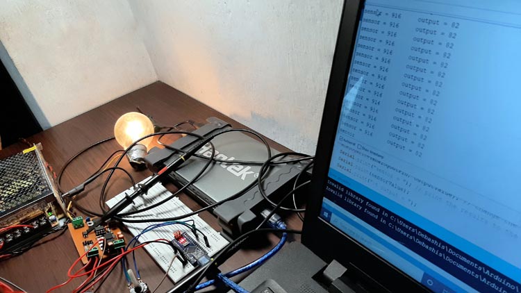
In this image, you can see that the value is 82, and the brightness of the incandescent light bulb increases.
After many failed attempts, I was able to come up with a circuit that actually works properly. Ever wondered how a test bench looks when a circuit doesn't work? Let me tell you it looks very bad,
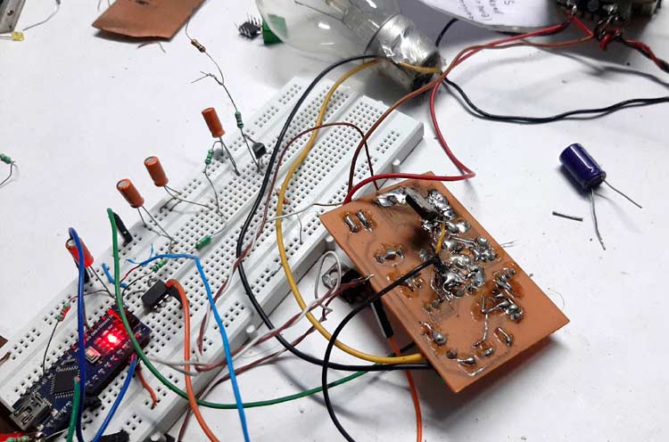
This is a previously designed circuit that I was working on. I had to completely throw it away and make a new one because the previous one was not working a bit.
Further Enhancements
For this demonstration, the circuit is made on a handmade PCB but the circuit can be easily built in a good quality PCB, in my experiments, the size of the PCB is really big due to the component size, but in a production environment, it can be reduced by using cheap SMD components, In my experiments, I found using a 7555 timer instead of a 555 timer increase the controlee extensively, furthermore, the stability of the circuit increase as well.
const int analogInPin = A0;  // Analog input pin that the potentiometer is attached to
const int analogOutPin = 9; // Analog output pin that the LED is attached to
int sensorValue = 0;        // value read from the pot
int outputValue = 0;        // value output to the PWM (analog out)
void setup() {
  // initialize serial communications at 9600 bps:
  Serial.begin(9600);
}
void loop() {
  sensorValue = analogRead(analogInPin);// read the analog in value:
  outputValue = map(sensorValue, 0, 1023, 0, 255);  // map it to the range of the analog out:
  //outputValue = map(sensorValue, 0, 1023, 0, 255);  // map it to the range of the analog out:
  analogWrite(analogOutPin, outputValue); // change the analog out value:
  Serial.print("sensor = "); // print the results to the Serial Monitor:
  Serial.print(sensorValue);
  Serial.print("\t output = ");
  Serial.println(outputValue);
  delay(2); // wait 2 milliseconds before the next loop for the analog-to-digital
}Comments
Kevin, You probably already
Kevin, You probably already solved your concern, but best I can tell the Control signal is an analog value. In his writeup he says "the P-Channel MOSFET acts as the variable resistor, which controls the charging time of the capacitor." I am not sure why he needs a PWM signal because the trigger is provided by the Zero Crossing Detection Circuit. Hope this helps.
Dear Sir,
Dear Sir,
Please elaborate more on the working of the timer. If the AC is 230 acV @ 50Hz, then zero crossing pulse will happens every 10 ms. If PWM is supplied by pin 9, then the frequency is 490Hz, which means that there will be pulse for every 2ms or 5 pulses of PWM for every pulse of ZC.
1 So how many pulses does the the timer produce (from pin 3) and how do you detemined / calculate it for each ZC?
2. How do you calculate the timing, T = 1.1RC (How do you determine R?)
3.Pin 6 (threshold) will only activate when the voltage is 2/3 Vcc, that is 2/3x9 = 6 V but the maximum voltage of PWM (with 100% duty cycle ) is only 5V. Does it means that Pin 6 will never be activated?
Thank you
Hello Sir,
Hello Sir,
I am sorry for the mistake in question no 3.
4. I am a bit confused about the passive low filter pass. Why do you need the filter since the PWM frequency is ( stable) at 490 Hz and from the formula
fc = 1 / 2πRCfc=1/2x3.142x82000x0.0000033 =0.588 Hz. It is true?
So that means that PWM frequency at 490Hz wont be able to pss through?
Hello everyone, Please I…
Hello Everyone,
Please I need to purchase a commercially available Phase Angle controlled voltage supply, of about 2KVA, 230-240V, 50/60Hz. Can I get this on Aliexpress or Amazon?
I would appreciate any help on this. Thank you
Kind Regards
One thing to note is that…
One thing to note is that this will not work with e.g. a MOC308x series which has built-in zero-crossing detection. This design specifically to ensures that the triac is activated at or near the zero-crossing point to reduce the electromagnetic interference and other noise generated when the triac is activated.
Obviously, since we're shooting for a specific time *after* the zero crossing for this circuit, those two constraints are in conflict and the MOC308x will do what it's supposed to do and hold the switch off until the next zero-crossing.
Also, I'm pretty sure the schematic symbol used for the MOC3021M is for one of the MOC308x (or other zero-crossing containing chip). The [1] symbol on the pin 4 pathway is how the zero-crossing circutry is shown though in KiCad, it has [zcd] instead. The MOC3021M has nothing there.


I built your AC Phase Angle Control circuit and am trying to drive it with a Raspberry Pi generating the PWM. My issue is that nothing seems to be getting to the 555's DIS/THR inputs. I have tried several different PWM Frequencies without success. What were you running for a PWM Freq in your example? The Low Pass Filter formed by the 82K and 3.3uF seems to have an extremely low cut-off frequency.