
Previously we have built Temperature controlled LEDs Circuit, in which two LEDs were glowing according to the temperature. Now we are enhancing that circuit by using a Relay, and now we are going to Control Home AC appliances according to Temperature. This circuit will serve as automatic light switch which will trigger if temperature goes beyond a particular level (50 Degree in this circuit). We are using LM35 as temperature sensor here. This threshold temperature of 50 degree value can be changed by adjusting the Variable resistor in the circuit, according to requirement.
We have used a simple LED bulb in this Temperature Controlled Switch Circuit for demonstration, means if temperature goes above than 50 Degree Celsius then bulb will switch on automatically and if temperature goes below 50 degree, bulb will be switched off automatically. Here you can replace the bulb by any AC home appliance, like if you replace it by fan then it will serve as Temperature Controlled Fan Circuit. It can also work as fire alarm if you set the threshold temperature very high like 100 Degree Celsius and connect a alarm in place of bulb or you can configure it to automatically switch on the Air Conditioner beyond a particular temperature by using a Relay of proper rating.
Required Components:
- 9v Battery
- IC 7805
- Temperature sensor LM35
- Op-amp LM358
- 10k ohm Resistor
- 1k ohm Resistor
- Variable Resistor 10k
- LED (optional)
- NPN Transistor BC547
- Diode 1N4007
- Relay 6v
- Bulb or any AC appliance
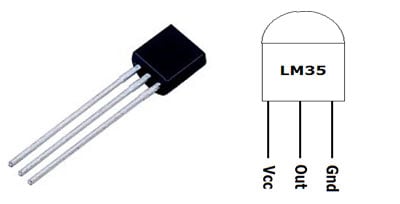
Temperature Sensor LM35:
LM35 is three pin transistor like device. It has VCC, GND and OUTPUT. This sensor provides variable voltage at the output based on temperature. LM35 provides output in degree Celsius and can sense up to 150 degree Celsius temperature. LM35 is very popular and inexpensive temperature sensor generally used as digital thermometer or to measure temperature.
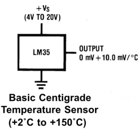
For every +1 centigrade rise in temperature there will be +10mV higher voltage at the output pin. So if the temperature is 0◦ centigrade the output of sensor will be 0V, if the temperature is 10◦ centigrade the output of sensor will be +100mV, if the temperature is 25◦ centigrade the output of sensor will be +250mV.
Setting up Reference Voltage for Op-amp LM358:
Here we have used Op-amp LM358 to compare the output voltage of LM35 with the reference voltage. As mentioned we have set the circuit for threshold voltage 50 Degree, so to trigger the op-amp at 50 Degree, we need to set the reference voltage to 0.5 volt, as at 50 degree temperature LM35 output voltage will be 0.5 volt or 500mV. Reference voltage is the voltage at Pin no 2 of LM358.
Now to set the reference voltage, we have created a Voltage Divider circuit by using resistor R1 and Variable resistor RV1 of 10k. By using the above formulae you can set the reference voltage accordingly and can change the Threshold Temperature. Like to set the 50 degree Celsius temperature as triggering value, you can set the potentiometer roughly at 8k:2k like:
Vout = (R2 / R1 + R2) * Vin
(here R2 is second part of potentiometer:2k ohm and R1 is R1 + first part of potentiometer: 10k+8k)
Vout = (2 / 18 + 2) * 5 = 0.5v
Op-amp LM358:
Op-amps are also known as Voltage Comparators. When voltage at non-inverting input (+) is higher than the voltage at inverting input (-), then the output of comparator is High. And if the voltage of inverting input (-) is Higher than non-inverting end (+), then output is LOW. Know more about working of op-amp here.
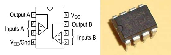
LM358 is a Dual Low Noise Operational Amplifier which has two independent voltage comparators inside. This is a general purpose op amp which can be configured in many modes like comparator, summer, integrator, amplifier, differentiator, inverting mode, non- inverting mode, etc.
Circuit Diagram:

Working Explanation:
Working of this Temperature Controlled Home Appliances Circuit is simple. 9v general purpose battery is used to power up the whole circuit and IC7805 is used to provide the regulated 5v supply to the circuit. When temperature is below 50 degree then output of LM358 remains LOW and transistor Q1 & Relay also remain in OFF state, thus bulb is off. You can set this threshold temperature accordingly by rotating the POT.
Now when surrounding’s temperature goes beyond 50 Degree Celsius, output voltage of LM35 at pin 2 also goes higher than 0.5 volt or 500mV. Output of LM35 is connected to Pin 3 of Op-amp LM358. And as we have set the reference voltage (voltage at Pin 2 of LM358) to 0.5 volt, so now voltage at Pin 3 (non-inverting input) becomes higher than voltage at Pin 2 (inverting input) and output of opamp LM358 (PIN 1) becomes HIGH. Output of LM358 is connected to the base of NPN transistor Q1, so Q1 also becomes ON which triggers the Relay and bulb gets turned ON. Relay has small coil inside which get energies by small current and trigger the AC device connected to it, we have explained its working below. So that’s how this circuit detects the temperature limit and automatically switch on the Appliances.
In the demonstration video, we have used soldering iron to heat up the surrounding near Temperature sensor LM35, check the video at the end. Also here we are working with direct AC mains of 220v, so extreme care must be taken, otherwise you may have a serious injury.
Working of Relay:
Relay is an electromagnetic switch, which allows much larger current to flow when a small current is applied to it, like we use transistor as a switch. Relay is generally used to control the AC (alternate current) devices, using a much smaller DC current.
Relay has a coil inside and when there is no voltage applied to the coil, COM (common) is connected to NC (normally closed contact). And when there is some voltage applied to the coil, the electromagnetic field produced. Which attract the Armature (lever connected to spring), and COM and NO (normally open contact) gets connected, which allow larger current to flow. Relays are available in many ratings, here we used 6V operating voltage relay, which allow 7A-250VAC current to flow.
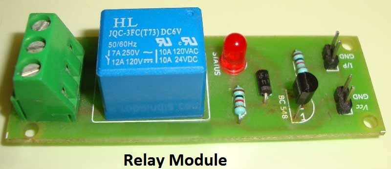
Relay is configured by using a small Driver circuit which consist a Transistor, Diode and a resistor. Transistor is used to amplify the current so that full current (from the DC source – 9v battery) can flow through coil to fully energies it. Resistor is used to provide biasing to transistor. And Diode is used to prevent reverse current flow, when the transistor is switched OFF. Every Inductor coil produces equal and opposite EMF when switched OFF suddenly, this may cause permanent damage to components, so Diode must be used to prevent reverse current. A Relay module is easily available in the market with all its Driver circuit on the board or you can create it by using above components. Here we have used 6V Relay module. You can further learn about the Relay here.
Comments
nice project
relay not on in this diagram and at pin 3 voltage always high then at pin 2
HI. I WOULD JUST WANT TO ASK FOR YOUR PERMISSION. I WILL BE USING YOUR DESIGN AS A PROPOSAL PROJECT TO ONE OF MY SUBJECTS. I WILL PUT A CREDIT SO THAT IT WILL BE CLEAR THAT IT WAS YOUR DESIGNED PROJECT. I HOPE YOU DON'T MIND. THANKYOU! PLEASE LET ME KNOW YOUR REAL NAME IF NOT I WILL PUT THE WEBSITE WHERE I GOT IT FROM,
hi
For a special use i need this PCB in - 3.v - power consumption.
i will have to use photovoltaic cell (solar cell) to charge a super capacitor - what the changes is needed?
please help me any one in this matter
thanks !
I need a circuit for temperature tolerance dictator in a way that it will be using lm35 and lm3914 and 10 leds so that the less will be connected to the lm3914 and it will be displaying the level of the temperature of any device
Plesce I need an answer immediately
nice

Nice information