
In this DIY, we are going to make an IOT based smart garbage alert system using Arduino uno that will tell us that whether the trash can is empty or full through the web server, and you can know the status of your ‘Trash Can’ or 'Garbage' from anywhere in the world over the Internet. It will be very useful and can be installed in the Trash Cans at public places as well as at home.
In this IOT Project, an Ultrasonic Sensor is used for detecting whether the trash can is filled with garbage or not. Here Ultrasonic Sensor is installed at the top of the Trash Can and will measure the distance of garbage from the top of the Trash Can, and we can set a threshold value according to the size of the trash can. If the distance is less than this threshold value, it means that the Trash can is full of garbage, and we will print the message “Basket is Full” on the webpage; and if the distance is more than this threshold value, then we will print the message “Basket is Empty”. Here we have set the Threshold value of 5cm in the Program code. We will use an ESP8266 Wi-Fi module to connect the Arduino to the web server. Here, we have used a Local web server to demonstrate the working of this IoT-based garbage monitoring system using Arduino.
Table of Contents
- Components Required for Smart Waste Management Using IoT Project
- HC-SR04 Ultrasonic Sensor IoT Garbage Monitoring
- ESP8266 Wi-Fi Module for Smart Waste Management
- ESP8266 Module Specifications
- Circuit Diagram and Explanation
- Code Explanation
- └ Ultrasonic Sensor Reading for Smart Waste Management
- Testing and Output of the Project:
- Explore the Implementation Details in Our GitHub Repository
- Frequently Asked Questions
- IoT Projects Featuring a Garbage Monitoring System
Components Required for Smart Waste Management Using IoT Project
- Arduino Uno (you can use any other)
- ESP8266 Wi-Fi module
- HC-SR04 Ultrasonic sensor
- 1K Resistors
- Breadboard
- Connecting wires
HC-SR04 Ultrasonic Sensor IoT Garbage Monitoring
The Ultrasonic Sensor is used to measure the distance with high accuracy and stable readings. It can measure distances from 2cm to 400cm or from 1 inch to 13 feet. It emits an ultrasound wave at the frequency of 40KHz in the air, and if the object comes in its way, then it will bounce back to the sensor. By using the time which it takes to strike the object and come back, you can calculate the distance.
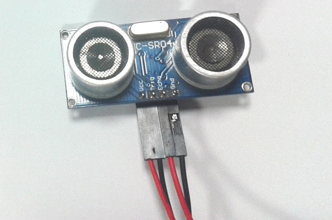
The ultrasonic sensor has four pins. Two are VCC and GND, which will be connected to the 5V and the GND of the Arduino, while the other two pins are Trig and Echo pins, which will be connected to any digital pins of the Arduino. The trig pin will send the signal, and the Echo pin will be used to receive the signal. To generate an ultrasound signal, you will have to make the Trig pin high for about 10us, which will send an 8-cycle sonic burst at the speed of sound, and after striking the object, it will be received by the Echo pin.
Further check projects below to properly understand the working of the Ultrasonic sensor and to measure the distance of any object using it:
- Arduino-Based Distance Measurement using Ultrasonic Sensor
- Distance Measurement using HC-SR04 and AVR Microcontroller
ESP8266 Wi-Fi Module for Smart Waste Management
ESP8266 is a Wi-Fi module that will give your projects access to Wi-Fi or the internet. It is a very cheap device, but it will make your projects very powerful. It can communicate with any microcontroller and make the projects wireless. It is in the list of most leading devices in the IOT platform. It runs on 3.3V, and if you will give it 5V then it will get damaged.
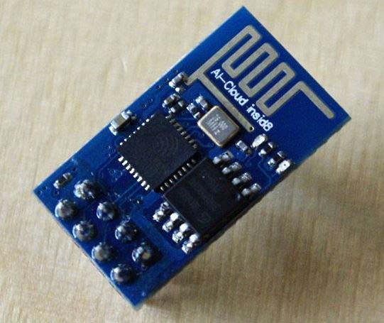
The ESP8266 has 8 pins; the VCC and CH-PD will be connected to the 3.3V to enable the wifi. The TX and RX pins will be responsible for the communication of ESP8266 with the Arduino. The RX pin works on 3.3V so you will have to make a voltage divider for it as we did in our project.
ESP8266 Module Specifications
Feature | Specification |
|---|---|
Operating Voltage | 3.3V DC |
Wi-Fi Standards | 802.11 b/g/n |
Frequency Range | 2.4GHz |
Communication | UART (TX/RX) |
Operating Modes | Station, Access Point, Both |

Circuit Diagram and Explanation
First of all, we will connect the ESP8266 with the Arduino. ESP8266 runs on 3.3V, and if you will give it 5V from the Arduino, then it won’t work properly and it may get damaged. Connect the VCC and the CH_PD to the 3.3V pin of Arduino. The RX pin of ESP8266 works on 3.3V, and it will not communicate with the Arduino when we connect it directly to the Arduino. So, we will have to make a voltage divider for it. Three 1k resistors connected in series will do the work for us. Connect the RX to the pin 11 of the Arduino through the resistors as shown in the figure below, and also the TX of the Arduino to the pin 10 of the Arduino.
Now it’s time to connect the HC-SR04 ultrasonic sensor with the Arduino. Connections of the ultrasonic sensor with the Arduino are very simple. Connect the VCC and the ground of the ultrasonic sensor to the 5V and the ground of the Arduino. Then connect the TRIG and ECHO pins of the ultrasonic sensor to the pins 8 and 9 of the Arduino, respectively.

Code Explanation
Before uploading the code, make sure that you are connected to the Wi-Fi of your ESP8266 device. You can check the full code in the Code section below, which has been well explained by the comments. Further, we have also explained some important functions below.
Ultrasonic Sensor Reading for Smart Waste Management
The Arduino will first read the Ultrasonic Sensor. It will send an ultrasonic signal at the speed of sound when we will make the TRIG pin high for 10us. The signal will come back after striking the object, and we will store the travel time duration in the variable named duration. Then we will calculate the distance of the object (garbage in our case) by applying a formula and will store it in the variable named distance.
digitalWrite(trigPin, LOW);
delayMicroseconds(2);
digitalWrite(trigPin, HIGH);
delayMicroseconds(10);
digitalWrite(trigPin, LOW);
duration = pulseIn(echoPin, HIGH);
distance= duration*0.034/2;
For printing the output on the webpage in a web browser, we will have to use HTML programming. So, we have created a string named webpage and stored the output in it. To tell whether the trash can is empty or not, we have applied a condition there. If the distance is less than 5cm, then it will show “Basket is Full” on the webpage, and if the distance is greater than 5cm, then it will show the message “Basket is Empty” on the webpage.
  if(esp8266.available())
  {
    if(esp8266.find("+IPD,"))
    {
     delay(1000);
     int connectionId = esp8266.read()-48;
     String webpage = "<h1>IOT Garbage Monitoring System</h1>";
       webpage += "<p><h2>";
       if (distance<5)
       {
        webpage+= " Trash can is Full";
        }
        else{
          webpage+= " Trash can is Empty";
          }
       webpage += "</h2></p></body>";
The following code will send and show the data on the webpage. The data, we stored in string named ‘webpage’, will be saved in string named ‘command’. The ESP8266 will then read the character one by one from the ‘command’ and will print it on the webpage.
String sendData(String command, const int timeout, boolean debug)
{
    String response = "";
    esp8266.print(command);
    long int time = millis();
    while( (time+timeout) > millis())
    {
      while(esp8266.available())
      {
        char c = esp8266.read();
        response+=c;
      }
    }
    if(debug)
    {
      Serial.print(response);
    }
    return response;
}
Testing and Output of the Project:
After uploading the code, open the Serial Monitor, and it will show you an IP address as shown below.
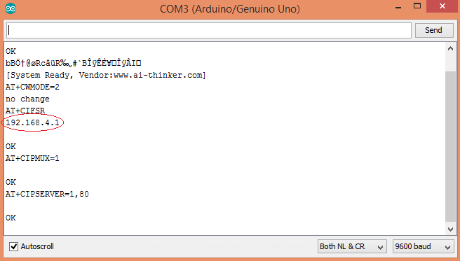
Type this IP address in your browser, it will show you the output as shown below. You will have to refresh the page again if you want to see again that the trash can is empty or not.
So this is how this Garbage Monitoring System works. This project can be further enhanced by adding a few more features to it, like we can set one more message when the Trash Can is half filled, or we can trigger an Email/SMS to alert the user when the Trash Basket is full making it a complete iot based smart waste management system using arduino.
Explore the Implementation Details in Our GitHub Repository
The main implementation techniques and architectural choices that support our application are fully explained in this section. To learn how important features are created and maintained, developers can look at the project's intricate code structure, design patterns, and technical methodologies.


Frequently Asked Questions
⇥ To what extent is the Internet of Things garbage monitoring system accurate?
The HC-SR04 ultrasonic sensor is very dependable for detecting the level of garbage in bins of different sizes because it has an accuracy of ±3mm within its 2cm to 400cm range.
⇥ Is it possible to use this smart garbage monitoring system outside?
Yes, but the electronics will need to be weatherproofed. While making sure the ultrasonic sensor is not obstructed, think about utilizing a waterproof enclosure for the Arduino and ESP8266.
⇥ Can I use a single Arduino to monitor several trash cans?
Yes, you can change the code to manage multiple bin monitoring at once by connecting multiple ultrasonic sensors to various digital pins on the Arduino.
IoT Projects Featuring a Garbage Monitoring System
We’ve used this Garbage Monitoring System in several engaging projects in the past. You can explore those articles through the links below.

Our IoT-Based Smart Bin project features a custom-built IoT system and Firebase database, using the Arduino Uno R4 WiFi. Dual ultrasonic sensors handle motion and fill-level monitoring, with an automated lid synced to a Firebase dashboard built on Vite+React for real-time updates.

Smart Dustbin using Arduino and Ultrasonic Sensor
Smart Dustbin as its name represents its work smartly or we can say that it is an automatic dustbin. Smart Dustbin is a very good project from the Arduino. We can say that It is a decent gadget to make your home clean and attractive. kids spread trash to a great extent by paper, rappers and numerous different things at home.

In this project, I will show you how to make a Smart Dustbin using Arduino, where the lid of the dustbin will automatically open when you approach with trash.
Complete Project Code
#include <SoftwareSerial.h>         // including the library for the software serial
#define DEBUG true
SoftwareSerial esp8266(10,11);      /* This will make the pin 10 of arduino as RX pin and
pin 11 of arduino as the TX pin Which means that you have to connect the TX from the esp8266
to the pin 10 of arduino and the Rx from the esp to the pin 11 of the arduino*/

const int trigPin = 8;            // Making the arduino's pin 8 as the trig pin of ultrasonic sensor
const int echoPin = 9;            // Making the arduino's pin 9 as the echo pin of the ultrasonic sensor
// defining two variable for measuring the distance
long duration;
int distance;
void setup()
{
  Serial.begin(9600);         // Setting the baudrate at 9600
  esp8266.begin(9600);        // Set the baudrate according to you esp's baudrate. your esp's baudrate might be different from mine
  pinMode(trigPin, OUTPUT);   // Setting the trigPin as Output pin
  pinMode(echoPin, INPUT);    // Setting the echoPin as Input pin

  sendData("AT+RST\r\n",2000,DEBUG);            // command to reset the module
  sendData("AT+CWMODE=2\r\n",1000,DEBUG);       // This will configure the mode as access point
  sendData("AT+CIFSR\r\n",1000,DEBUG);          // This command will get the ip address
  sendData("AT+CIPMUX=1\r\n",1000,DEBUG);       // This will configure the esp for multiple connections
  sendData("AT+CIPSERVER=1,80\r\n",1000,DEBUG); // This command will turn on the server on port 80
}
void loop()
{
digitalWrite(trigPin, LOW);   // Making the trigpin as low
delayMicroseconds(2);         // delay of 2us
digitalWrite(trigPin, HIGH); // making the trigpin high for 10us to send the signal
delayMicroseconds(10);
digitalWrite(trigPin, LOW);
duration = pulseIn(echoPin, HIGH);  // reading the echopin which will tell us that how much time the signal takes to come back
distance= duration*0.034/2;         // Calculating the distance and storing in the distance variable

  if(esp8266.available())         // This command will that check if the esp is sending a message
  {
    if(esp8266.find("+IPD,"))
    {
     delay(1000);
     int connectionId = esp8266.read()-48; /* We are subtracting 48 from the output because the read() function returns
                                            the ASCII decimal value and the first decimal number which is 0 starts at 48*/
     String webpage = "<h1>IOT Garbage Monitoring System</h1>";
       webpage += "<p><h2>";
       if (distance<5)
       {
        webpage+= " Trash can is Full";
        }
        else{
          webpage+= " Trash can is Empty";
          }
       webpage += "</h2></p></body>";
     String cipSend = "AT+CIPSEND=";
     cipSend += connectionId;
     cipSend += ",";
     cipSend +=webpage.length();
     cipSend +="\r\n";
     sendData(cipSend,1000,DEBUG);
     sendData(webpage,1000,DEBUG);
     String closeCommand = "AT+CIPCLOSE=";
     closeCommand+=connectionId;
     closeCommand+="\r\n";
     sendData(closeCommand,3000,DEBUG);
    }
  }
}

String sendData(String command, const int timeout, boolean debug)
{
    String response = "";
    esp8266.print(command);
    long int time = millis();
    while( (time+timeout) > millis())
    {
      while(esp8266.available())
      {
        char c = esp8266.read();
        response+=c;
      }
    }
    if(debug)
    {
      Serial.print(response);
    }
    return response;
}
Comments
Change the baud rate. Your esp8266 may have different baud rate.
its not working still
Check your TX and RX are connected to right pins and if it is still not running then try to power esp8266 from other source .
i used the 1k resistor to the it coming the ouput range is 4.6 i tested with my mulitmeter
and also i used the external source it not working there is nthg in the serial mointoring
First of all pls connect ur lappy wifi to the esp8266 network and then try it
If I compile the code it shows..
Send data is not declared in this scope..how to verify it.
Having trouble at this part of code: if(esp8266.find("+IPD,"))
I dont know why it is not working....
can i add two ultra sonic sensor. and can i get the two bins status on web server ??????????
Yes you can.
Bro if u did your project using two ultrasonic sensors can u please send me your arduino code to my email
should the wifi module be separately programmed ?
First i tested my esp8266 module,it is working but when i run the above program as per given instructions,Iam not seeing anything in the serial monitor.Please help me with this.
it shows me excess memory space declaration, error what to do
Good work. just want to ask, I want to fetch that result into an android app. Is it possible? i mean , that generated IP, is it static? if so, then i can easily fetch that IP into my app code. and then can display the result.
You can set ESP8266 module for using static IP with AT command like that: AT+CIPSTA="IP_address","Gateway","subnet_mask" or AT+CIPSTA="192.168.1.120","192.168.1.1","255.255.255.0". ESP8266 remembers the last settings so the IP will remain static.
ESP8266 module is not able to connect with internet as it is showing me "limited".
what should be done?
Check our various ESP8266 projects with Arduino here to properly interface ESP: https://circuitdigest.com/arduino-esp8266-projects
After uploading the coDe nothing appear onto the serial monitor plz help
Sir I am unable to upload the code in the audrino can you please help me? I will be thankful to you
I'm getting garbage values on my serial monitor, can someone please help
After uploading code nothing appears on serial monitor
how to setup a software for this wifi module in order to get the output i mean in the starting which board must i select
First learn to use ESP8266 here: Getting Started with ESP8266
sir how much cost for prepare to took iot dumpster monitoring usinig arduino and esp8266
It will be less than INR 1000, including all components and Arduino.
m not able to obtain the IP address plz help
Any idea how to connect this to a thingspeak channel?
You should upload that through an API key. Use the api key for connections.
when doing this project while I connect my wifi module to 3.3v pin in Arduino it shows the port error.
Like "error opening serial port 'COM3'". how many times I changed the port it is showing like that.
When I remove the wifi module 3.3V pin from Arduino it shows me to port and I can upload all the codes.
Why that happens.....??
this code not working. output have an error
why i cant use AT command
Ofcourse you can use AT commands. If you take a closer look at the Arduino program, it is actually the AT commnads that are being sent to the ESP8266 through Arduino Program
i have made the hardware and uploaded the code but when i enter the link in chrome it save proxy script to my computer and after that thrash can is empty appears on my serial monitor not webpage please suggest solution its urgent
how to connect to the wifi of esp8266?
Configure the ESP in AP (Access Point) mode and you should be able to find the device on your WIFI device manager on Phone/Computer. Then simply connect to it
when i upload this code and connect other wifi module and sensor with arduino board . Its not display serial monitor and 192.168.4.1. this server is not working.. what can i do now.. please help.
avrdude: ser_open() : can't open device "\\.\COM4": The system cannot find the file specified
Hi kavitha,
This error is because you have selected the wrong COM port. use device manager to check to which com port your arduino is connected and select the same
Do we need to download any package for the esp8266
Yes the library mentioned by the author has to be downloaded and added to arduino IDE
after uploading the code in the Arduino there is nothing will appear in the serial monitor.how can i refer whether it is working or not.
Understand the code and use some Serial.pritln() line inside the code to check upto which part the code is executing (you can use serial monitor)
Also try some basic ESP projects before this one
How to make sure that the setup is connected to the wifi of esp8266-01?... the serial monitor is not displaying anything
If serial monitor shows nothing it means you have not connected the circuit properly. Use a multimeter to check for voltage levels.
Could u pls send me d code for iot garbage monitoring system using Blynk app
This is working
nothing is displaying in the serial monitor can us plz tell me what we have to send to display ip adress
Hello...there is no error in my code.i uploaded it successfully.but it was not show anything in serial monitor.is there any connections need for further proceedings.plz help me...
hey, I have ESP8266 NodeMCU in which there are many pins then what will be the ch_pd and Vcc in that? in short how I will connect the ESP8266 NodeMCU to Arduino now? please help.
is it OK if I will add A 2 Ultrasonic sensor?
How to solve the error espcomm_upload_mem failed
please help
We should upload code in arudiuno uno only ?? Or can we upload in esp8266 it will work or not ??
Having trouble at this part of code: if(esp8266.find("+IPD,"))
I dont know why it is not working. Help me guysss
avrdude: stk500_recv(): programmer is not responding
error is coming
after all IP address typing in browser it is showing oops!could not connect to i
Hello, i am facing the same trouble, the website could be connected, [email protected], it would be a great help if you help me out if you have solved it
I burned the code at 115200 baud rate. Serial monitor is showing ip address and all but that ip address does not open in browser. Site cant be reached is shown.
getting bad characters in serial monitor though have set the baudrate same as in the program.
what to do??
Try some other code and check if you serial monitor is working properly. Also send what "bad characters" you are getting. This will help us sort out the issue
v r getting some junk characters what do we do??
nothing displayed on serial monitor...what to do??
This code is uploaded successfully but nothing shows in the serial monitor. What have to do? please help me..It's emergency.
can change to reading counter or not ?
even if the code is uploaded successfully ,when we open serial monitor it is showing blank
can u plz reply its urgent
From where I get all these equipment. Online or in shop.I am living in mumbai.
hello!buddy serial monitor is not showing anything. I connected it the way u did. what to do?
I follow the all the step and did the connection as per the diagram but ESP8266 is not visible to connect the lappy, what should I do??
warning: espcomm_sync failed
this rror coming please do reply fst
how to solve this error

after uploding the code ...nothing appears in my serial monitor screen..please so help