
In the modern world, we use batteries in almost every electronic gadget from your handheld mobile phone, digital thermometer, smartwatch to Electric Vehicles, aeroplanes, satellites, and even Robotic Rovers used on Mars whose battery lasted around 700 sols (Martian days). It is safe to say without the invention of these electrochemical storage devices a.k.a. Batteries, the world as we know it would not exist. There are many different types of batteries like Lead-Acid, Ni-Cd, Lithium-Ion, etc. With the advent of technology, we are seeing new batteries invented like Li-air Batteries, Solid State Lithium batteries, etc. which have higher energy storage capacity and high operating temperature range. We have already discussed more about batteries and how they work in our previous articles. In this article, we will learn how to design a simple 12V battery charge level indicator using Op-Amp.
Although the Battery level is an ambiguous term because we can't really measure the charge left in the battery unless we employ complex calculations and measurements using a Battery Management System. But in simple applications, we do not have the luxury of this method so we usually employ a simple Open Circuit Voltage based Battery Level Estimation method which works really well for Lead Acid 12V batteries as their discharge curve is almost linear from 13.8V to 10.1V, which usually are considered its upper and lower extreme limits. Previously we have also built an Arduino based battery level indicator and a Multiple Cell Voltage monitoring circuit, you can also check them out if you are interested.
In this project, we will design and build a 12V battery level indicator with the help of a quad comparator OPAMP based IC LM324 which lets us use 4 OPAMP based comparators on a single chip. We will measure the voltage of the battery and compare it against the prespecified voltage using the LM324 IC and drive the LEDs to display the output we get. Let us jump right into it, Shall we?
Components Required
- LM324 Quad OPAMP IC
- 4×LED Lights (Red)
- 1×2.5kΩ Resistor
- 5×1kΩ Resistor
- 1×1.6kΩ Resistor
- 4×0.5kΩ Resistor
- 14 Pin IC Holder
- PCB Screw Terminal
- Perfboard
- Soldering Kit
LM324 Quad OPAMP IC
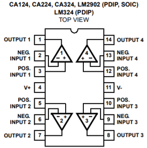
LM324 is a Quad op-amp IC integrated with four op-amps powered by a common power supply. The differential input voltage range can be equal to that of the power supply voltage. The default input offset voltage is very low which is of magnitude 2mV. The operating temperature ranges from 0˚C to 70˚C at ambient whereas the maximum junction temperature can be up to 150˚C. Generally, op-amps can perform mathematical operations and can be used in various configurations like Amplifier, voltage follower, comparator, etc. So, by employing four OPAMPs in a single IC, you will save space and complexity of the circuit. It can be powered by a single power supply over a wide voltage range of -3V to 32V which is more than enough for up to 24V battery level testing on this circuit.
Circuit Diagram for 12V Battery Level Indicator
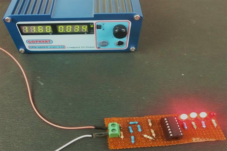
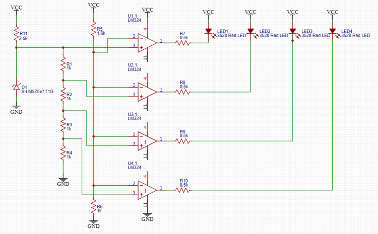
The complete circuit used in the 12V battery indicator can be found below. I have used a 9V battery for illustration purpose in the image below, but assume it as a 12V battery.

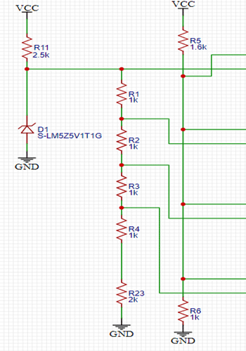
If you do not like graphical circuits, you can check the below image for the schematics. Here Vcc and Ground are the terminals that have to be connected to 12V battery positive and negative respectively.
Now, let’s proceed with understanding the working of the circuit. For the sake of simplicity, we can divide the circuit into 2 different parts.
Reference Voltages Section:
First, we need to decide which voltage levels we want to measure in the circuit, and you can design your resistor based potential divider circuit accordingly. In this circuit, D2 is a reference Zener Diode which is rated 5.1V 5W so it will regulate the output to 5.1V across it. There are 4 1k Resistance connected across it in series to the GND so approximately 1.25V drop will be there across every resistor which we will use for making comparisons with the battery voltage. The reference voltages for comparison are approximately 5.1V, 3.75V, 2.5V, and 1.25V.
Also, there is another voltage divider circuit that we will use to compare the battery voltages to the voltages given by the voltage divider connected across Zener. This voltage divider is important because by configuring its value, you will decide the voltage points beyond which you want to light up the corresponding LEDs. In this circuit, we have chosen 1.6k Resistor and 1.0k Resistor in series to provide a dividing factor of 2.6.
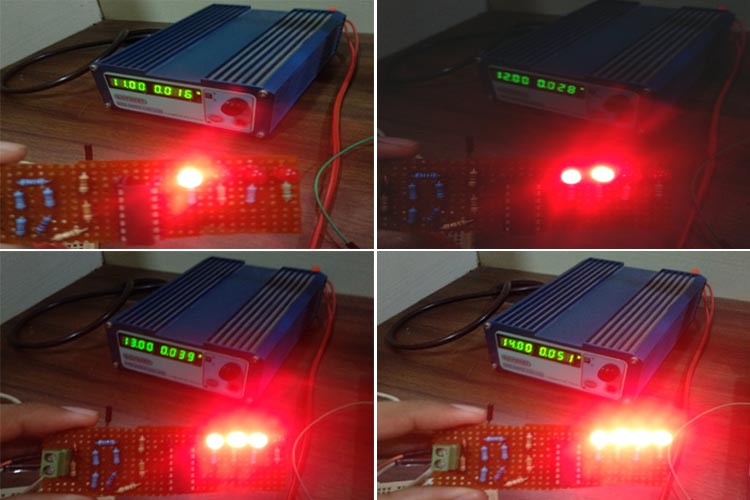
So if the upper limit of the Battery is 13.8V, then the corresponding voltage given by the potential divider will be 13.8/2.6=5.3V which is more than 5.1V given by the first reference voltage from Zener diode hence all the LEDs will be lit if the voltage of the battery is 12.5V i.e. neither fully charged nor fully discharged, then the corresponding voltage will be 12.5/2.6=4.8V which means it is less than 5.1V but greater than the other three reference voltages so three LEDs will light up and one won't. So, in this way, we can determine the voltage ranges for lighting up an individual LED.
Comparator and LED Section:
In this portion of the circuit, we are just driving the Different LEDs for different voltage levels. Since IC LM324 is an OPAMP based comparator so whenever the non-inverting terminal of a particular OPAMP is at a higher potential than the inverting terminal, the OPAMP output will be pulled high to the approximately VCC voltage level which is the battery voltage in our case. Here the LED won't light because the voltages at both Anode and Cathode of the LED are equal so no current would flow. If the Inverting terminal’s voltage is higher than the non-inverting terminal’s, then the output of the OPAMP will be pulled down to the GND level hence the LED will light up because it has a potential difference across its terminals.
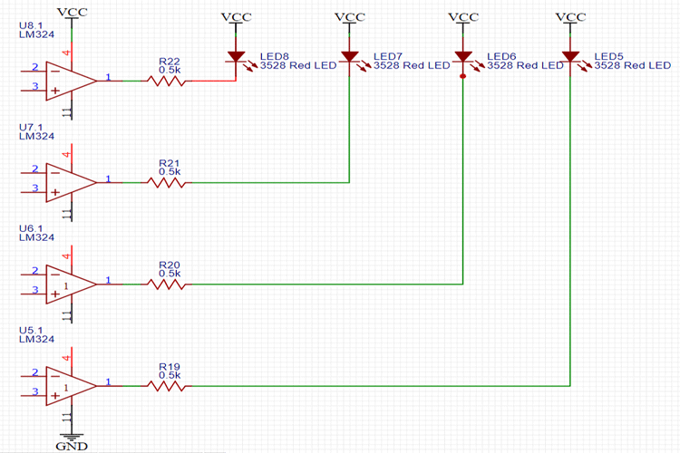
In our circuit, we have connected the non-inverting terminal of each OPAMP to the 1kΩ resistor of the potential divider circuit connected across the battery, and Inverting terminals are connected to the different voltage levels from the potential divider connected across the Zener. So, whenever the apportioned voltage of the battery is lower than the corresponding reference voltage of that OPAMP, the Output will be pulled high and the LED won't Light as explained earlier.
Challenges and Improvements:
It is a rather crude and basic method of approximating the voltage of the battery and you can further modify it to read a range of the voltage to your choice with adding an additional resistor in series with the potential divider connected across the 5.1V Zener diode, in this way, you can get more accuracy on a smaller range so that you can identify more voltage levels across a smaller range for real-world applications like for a lead-acid battery.
You can also interface different colored LEDs for different voltage levels and if you want a bar graph. I have only used a single LM324 in this circuit to keep it simple, you can use n number of Comparator ICs and with n resistors, in series with the reference voltage Zener diode, you can have as many reference voltages to compare against as you want which will further increase the accuracy of your indicator.
Building and Testing our 12V Battery Level Indicator
Now as we are finished designing the circuit, we need to fabricate it on the perf board. If you want, you can also test it on a breadboard first to see its working and debug the mistakes you might see in the circuit. If you want to save the hassle of soldering all the components together, you can also design your own PCB on AutoCAD Eagle, EasyEDA, or Proteus ARES or any other PCB Designing software you like.
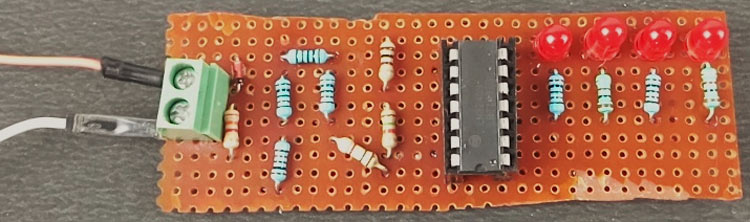
As the LM324 can work on a wide range of power supply ranging from -3V to 32V, you don’t have to worry about providing any separate power supply to the LM324 IC so we have used only one pair of PCB Screw Terminals which will be directly connected to the battery terminals and power the whole PCB. You can check for Voltage levels from Min 5.5V to a maximum of 15V by using this Circuit. I strongly recommend you add another resistor in series in the potential divider across the Zener and decrease the voltage range of each LED.
If you want to increase the voltage testing range from 12V to 24V as the LM324 is capable of testing up to 24V battery, you just have to change the voltage dividing factor of the voltage divider connected across the battery to make them comparable to voltage levels given by the Zener reference circuit and also, double the Resistances connected with the LEDs to safeguard it against the high current flow through them.
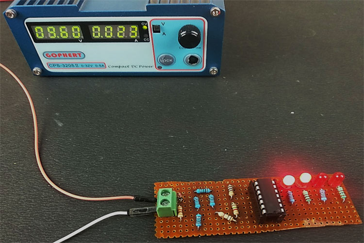
The complete working of this tutorial can also be found in the video linked below. Hope you enjoyed the tutorial and learned something useful if you have any questions, leave them in the comment section or you can use our forums for other technical questions.
