The NE555 is a popular IC that functions as a timer or an oscillator. It’s an 8-pin IC available in various packages. We are using an SOP-8 package of the IC. Due to the versatile functioning of the IC, it is used for various applications in projects as well as inside the circuitry of small toys to big electronic devices. There are three different modes in which IC operates: Astable (produces oscillation without triggering), Monostable (also known as timer circuit), and Bistable (requires triggering to change the state).
In this project, we use the monostable mode of the IC in which one state is stable but the other is unstable. A triggering is required to change the output from a stable to an unstable state.
Components required:
-
Breadboard
-
9v Battery & its connector
-
Push button
-
SOP-6 PCB Board
-
Male Header Pins
-
100k(1), 10k(2), 1k(1) resistor
-
100 µF Capacitor
-
BC547 transistor
-
Jumper Wires & Single strand Wire
-
Single Channel Relay Module
-
AC wire & Plug
-
AC bulb and bulb holder
The NE55 IC used is in the SOP package which can’t be easily fixed in the breadboard. The SOP-8 PCB board requires breadboard interfacing. The PCB board has printed numbers on it, matching the IC to the PIN. Solder the IC Legs and male headers to the PCB board.

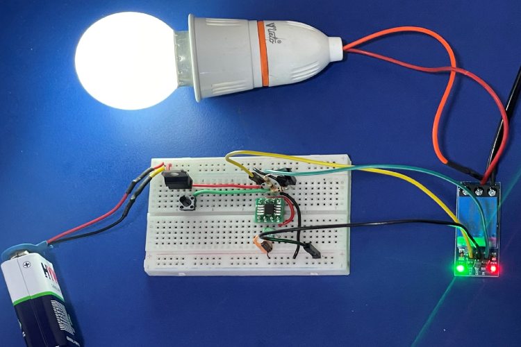
Timer-based Automatic Light Circuit
-
We are using L7805 IC for conversion of 9v to 5v. The IC has three pins Input, Output, and GND. The 9v is provided to input where the 5v is taken from the OUT pin. The GND pin is simply connected to the -ve of the battery terminal.
-
The output 5v is used to drive 555 and Relay. The 555-timer connection (as shown above) in the monostable mode includes a 100uf capacitor and 100k resistor to set the timer delay of the IC. The timing can easily be calculated by: T = 1.1 * R1*C1
-
The output is obtained from Pin 3 on the IC. The output is high in unstable mode means the LED will glow when u press the button for a certain time if u involve an LED there. The transistor and its both 1k and 10k resistors are used to invert the logic or basically functioning of NOT Gate because our relay module is activated on invert input.
-
If your relay module is not reversed logic activated, then you simply skip the transistor section. Directly provide IC output to relay input.
-
The output of the transistor collector is the input of the relay module and the other two pins for powering the relay module. The AC end connection is fully separated & and easy to understand.
Demonstration of timer-based Automatic Light
After all the successful timer-based connections, you can test it with a small LED bulb on the OUT and GND of the IC. Pressing the push button led to start the timer i.e., the LED started glowing. That’s how you initially checked your timing circuit before introducing the relay and logic invert.
Precautions:
-
All the wires must be tightly connected to the breadboard, otherwise, it leads to circuit failure.
-
Necessary steps should be taken while working on AC. Check the wiring 2-3 times before powering AC.
Now the circuit is ready for fully functioning, you can proof it by pressing the push button, and you will see that after around half in, the AC bulb is turned OFF.
.jpg)


