Road stud lights are highly visible reflective devices that are strategically installed on road surfaces to ensure safety during nighttime driving. These stud lights serve the purpose of guiding vehicles to maintain their lane and effectively navigate the road. Typically placed along lane markings or in the centre of the road, stud lights play a vital role in assisting motorists, particularly in areas lacking street lighting or when visibility is impaired due to inclement weather conditions like rain or snow. These illuminating devices help improve visibility by reflecting light, allowing drivers to have a clear view of the road ahead. This, in turn, reduces the likelihood of accidents and promotes overall road safety. Even though reflective-type stud lights are ok for normal conditions, active stud lights are needed in harsh environments. Not only that stud lights with built-in LED will provide much better visibility even in very dark areas.
So, in this project, we are going to build such a stud light. The main highlight is that it will be solar-powered and doesn’t need any external power. During the daytime, the inbuilt solar panel will charge up the internal battery and during the night this stored energy will be used to illuminate built-in LEDs.
Features of Solar Stud Light
- Solar Powered.
- Dedicated solar charge controller with built-in maximum power point tracking.
- Constant current LED driver for increased battery life and extended LED lifespan.
- Components with ultra-low power usage during inactivity.
Components Required to Build the Solar Stud Light
All the parts you will require to build the Solar Stud Light are listed below. The exact value of each component can be found in the schematics or the BOM.
- LT3562EMSF Solar Charge Controller IC x1.
- AD8542 Operational Amplifier x1.
- TLC555C Timer chip x1.
- MAX1916 LED driver IC x1.
- 10mm Red LEDs x6.
- SMD Resistors
- SMD Capacitors
- Wires
- Custom PCB
- 3D printed enclosure.
- Other tools and miscellaneous.
Solar Stud Light Circuit Diagram
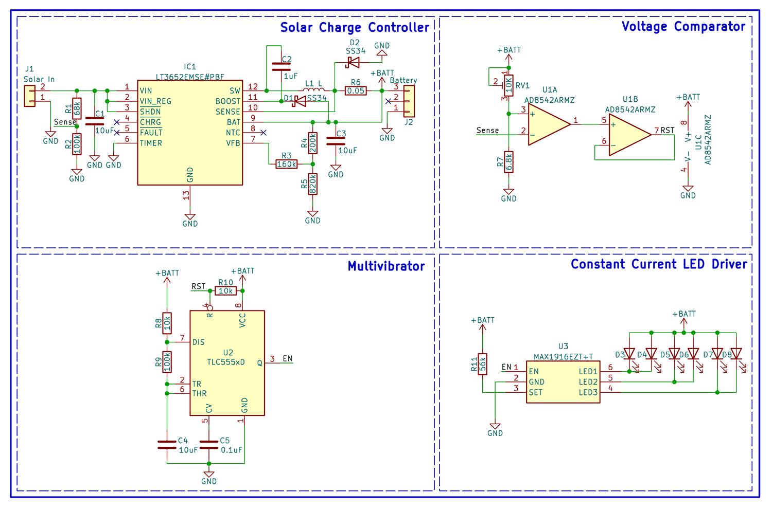
The complete circuit diagram for the Solar Stud Light is shown below.
The circuit itself is pretty simple. The schematics are divided into four parts for better understanding. The first section is the solar charge controller section. The charge controller is built around Analog Device’s LT3652EMSF charge controller chip with built-in MPPT(Maximum PowerPoint Tracking). It supports a wide input voltage range of 4.95V to 32V, making it compatible with a wide range of solar panels. It can charge up the battery with a maximum current of 2A and also features a charge termination timer for extended battery life.
The second stage is a voltage comparator for light sensing. It is built around the AD8542 operational amplifier from Analog Devices. The comparator circuit will monitor the voltage from the solar panel and will control the rest signal of the 555 timer chip used as the multivibrator. The comparator will pull down the reset line during the day, thus turning off the timer chip. During the night the voltage from the solar panel will be reduced and the comparator will pull up the reset line. The light sensitivity can be adjusted using the inboard variable resistor.
The third stage is the multivibrator stage. It is built around the popular 555 timer chip. We have used the TLC555C variant to make sure the proper working even at lower voltages. The multivibrator will generate a square wave with a frequency of around 0.6Hz.
The final stage consists of the MAX1916 LED driver chip along with the 10MM LEDs. The MAX1916 has three control channels and we are using each channel to drive two LEDs each. Each channel can sink up to 60mA. The current can be set using the current setting resistor. I have configured the current to 20mA per channel. This will give enough brightness and will save power and extend the life span of LEDs.
Solar Stud Light PCB

For convenience, I have designed a small PCB for the project. The PCB has a size of around 65x65mm. It will fit perfectly within the enclosure. JST connectors are provided for both solar input and the battery. Which will make it easier to assemble as well as service the stud light. The trimmer resistor onboard can be used to adjust the light sensitivity. You can find the full schematics as well as the Gerber files for the PCB from the link at the end of this article. Since the PCB only has a few components, I have decided to make a homemade PCB instead of manufacturing one from a vendor. The PCB turned out to be fine and works well. Here is the fully assembled PCB inside the enclosure.

And here is the fully build stud light.

3D Printed Parts

I have designed a small and compact enclosure for the stud light. It is printed with PLA with an infill percentage of 20. The Enclosure will not only make the project compact and easy to install, but it will also protect the circuit from dust and other debris. The enclosure can be waterproofed by applying silicon sealant before closing it. You can find the STL files for the Enclosure at the link.
Working
In the video below you can see the operation of the solar stud light. You see that while there is light the stud light will be in sleep mode and only the charging will be active. As soon as we block the light the is blocked the LEDs will start to blink at a frequency of around 0.6Hz.
You can download all the necessary files from the Circuit Digest GitHub repo.

