

Stepper motors is a brushless DC motor that rotates in discrete steps, and are the best choice for many precision motion control applications. Also, stepper motors are good for positioning, speed control and applications which require high torque at low speed.
In previous tutorials of MATLAB, we have explained that how to use MATLAB to control DC motor, Servo motor and Home appliances. Today we will learn how to control Stepper Motor using MATALB and Arduino. If you are new to MATLAB then it is recommend to get started with simple LED blink program with MATLAB.
Modes of operation in Stepper Motor
Before you start coding for stepper motor you should understand the working or rotating concept of a stepper motor. Since the stator of the stepper mode is built of different pairs of coils, each coil pair can be excited in many different methods, this enabling the modes to be driven in many different modes. The following are the broad classifications
Full Step Mode
In full step excitation mode we can achieve a full 360° rotation with minimum number of turns (steps). But this leads to less inertia and also the rotation will not be smooth. There are further two classifications in Full Step Excitation, they are one Phase-on wave stepping and two phase-on mode.
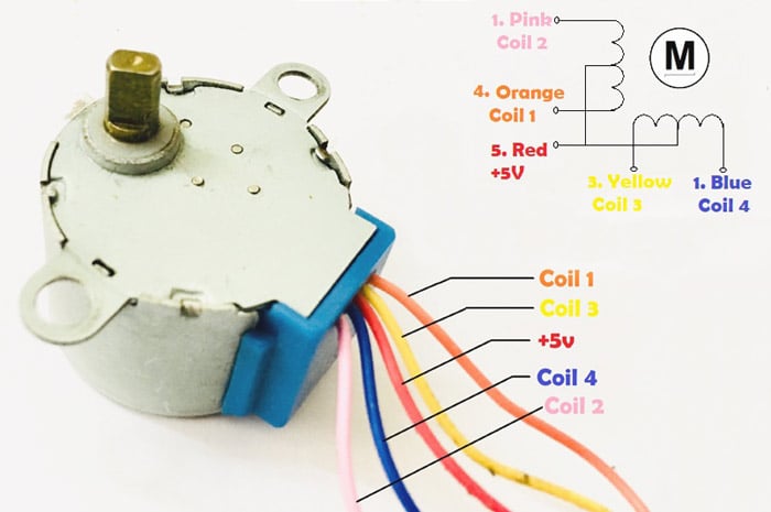
1. One phase-on stepping or Wave Stepping: In this mode only one terminal (phase) of the motor will be energised at any given time. This has less number of steps and hence can achieve a full 360° rotation. Since the number of steps is less the current consumed by this method is also very low. The following table shows the wave stepping sequence for a 4 phase stepper motor
| Step | Phase 1 (Blue) | Phase 2 (Pink) | Phase 3 (Yellow) | Phase 4 (Orange) |
| 1 | 1 | 0 | 0 | 0 |
| 2 | 0 | 1 | 0 | 0 |
| 3 | 0 | 0 | 1 | 0 |
| 4 | 0 | 0 | 0 | 1 |
2. Two Phase-on stepping: As the name states in this method two phases will be one. It has the same number of steps as Wave stepping, but since two coils are energised at a time it can provide better torque and speed compared to the previous method. Although one down side is that this method also consumes more power.
|
Step |
Phase 1 (Blue) |
Phase 2 (Pink) |
Phase 3 (Yellow) |
Phase 4 (Orange) |
|
1 |
1 |
1 |
0 |
0 |
|
2 |
0 |
1 |
1 |
0 |
|
3 |
0 |
0 |
1 |
1 |
|
4 |
1 |
0 |
0 |
1 |
Half Step Mode
The Half Step mode is the combination of one phase-on and two-phase on modes. This combination will help us to get over the above mentioned disadvantage of the both the modes.
As you might have guessed it since we are combining both the methods we will have to perform 8-steps in this method to get a complete rotation. The switching sequence for a 4-phase stepper motor shown below
|
Step |
Phase 1 (Blue) |
Phase 2 (Pink) |
Phase 3 (Yellow) |
Phase 4 (Orange) |
|
1 |
1 |
0 |
0 |
0 |
|
2 |
1 |
1 |
0 |
0 |
|
3 |
0 |
1 |
0 |
0 |
|
4 |
0 |
1 |
1 |
0 |
|
5 |
0 |
0 |
1 |
1 |
|
6 |
0 |
0 |
0 |
1 |
|
7 |
1 |
0 |
0 |
1 |
|
8 |
1 |
0 |
0 |
0 |
Hence, it is your choice to program your stepper motor in any mode, but I prefer Two Phase-on stepping Full Step Mode. Because this method deliver faster speed then the one phase method and in compare to half mode the coding part is less due to less number of steps in two-phase method.
Learn more about stepper motors and its modes here
Creating MATLAB Graphical User Interface for controlling Stepper Motor
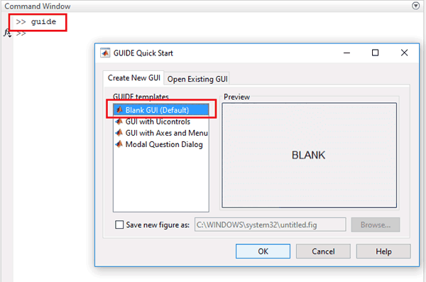
Then we have to build GUI (Graphical User Interface) to control Stepper motor. To launch the GUI, type the below command in the command window
guide
A popup window will open, then select new blank GUI as shown in below image,
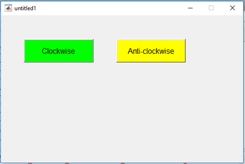
Now choose two toggle buttons for rotating the stepper Motor Clockwise and Anti-clockwise, as shown below,
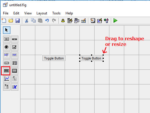
To resize or to change the shape of the button, just click on it and you will be able to drag the corners of the button. By double-clicking on toggle button you can change the color, string and tag of that particular button. We have customized two buttons as shown in below picture.
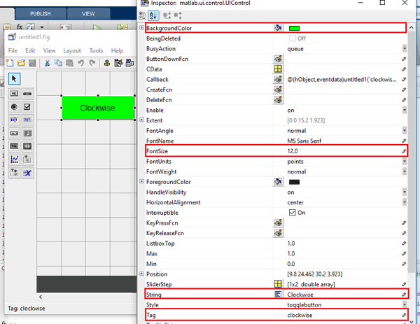
You can customize the buttons as per your choice. Now when you save this, a code is generated in the Editor window of MATLAB. To code your Arduino for performing any task related to your project, you always have to edit this generated code. So below we have edited the MATLAB code. You can learn more about Command window, editor window etc in Getting started with MATLAB tutorial.
MATLAB Code for controlling Stepper Motor with Arduino
Complete MATLAB code, for controlling Stepper motor, is given at the end of this project. Further we are including the GUI file (.fig) and code file(.m) here for download (right click on link then select 'Save link as...')), using which you can customize the buttons as per your requirement. Below are some tweaks we did for rotating the Stepper Motor clockwise and anticlockwise using two toggle buttons.
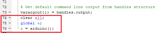
Copy and paste the below code on line no. 74 to make sure that the Arduino is talking with MATLAB every time you run the m-file.
clear all;
global a;
a = arduino();
When you scroll down, you will see that there are two functions created for both the Buttons in the GUI. Now write the code in both the functions according to the task you want to perform on click.
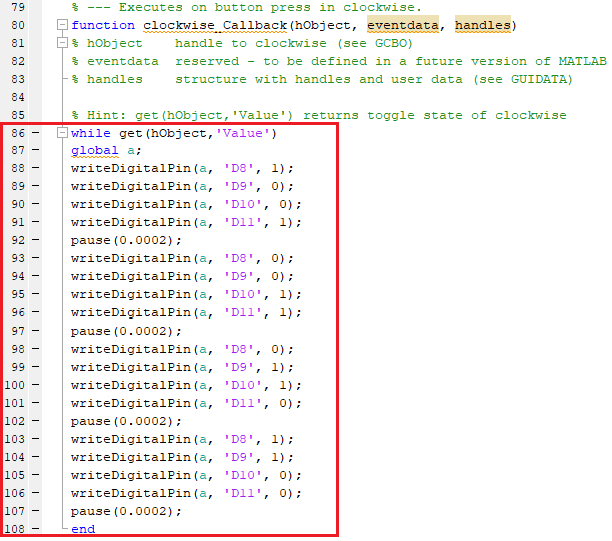
In Clockwise button’s function, copy and paste the below code just before the end of the function to rotate the motor in clockwise direction. For continuously rotating the stepper motor in clockwise direction, we are using while loop to repeat the two phase-on stepping full mode steps for clockwise direction.
while get(hObject,'Value')
global a;
writeDigitalPin(a, 'D8', 1);
writeDigitalPin(a, 'D9', 0);
writeDigitalPin(a, 'D10', 0);
writeDigitalPin(a, 'D11', 1);
pause(0.0002);
writeDigitalPin(a, 'D8', 0);
writeDigitalPin(a, 'D9', 0);
writeDigitalPin(a, 'D10', 1);
writeDigitalPin(a, 'D11', 1);
pause(0.0002);
writeDigitalPin(a, 'D8', 0);
writeDigitalPin(a, 'D9', 1);
writeDigitalPin(a, 'D10', 1);
writeDigitalPin(a, 'D11', 0);
pause(0.0002);
writeDigitalPin(a, 'D8', 1);
writeDigitalPin(a, 'D9', 1);
writeDigitalPin(a, 'D10', 0);
writeDigitalPin(a, 'D11', 0);
pause(0.0002);
end
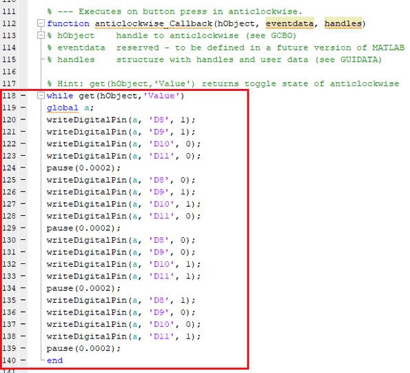
Now in Anti-clockwise button’s function, paste the below code at the of the function to rotate the motor in anti-clockwise direction. For continuously rotating the stepper motor in anti-clockwise direction, we are using while loop to repeat the two phase-on stepping full mode steps for anti-clockwise direction.
while get(hObject,'Value')
global a;
writeDigitalPin(a, 'D8', 1);
writeDigitalPin(a, 'D9', 1);
writeDigitalPin(a, 'D10', 0);
writeDigitalPin(a, 'D11', 0);
pause(0.0002);
writeDigitalPin(a, 'D8', 0);
writeDigitalPin(a, 'D9', 1);
writeDigitalPin(a, 'D10', 1);
writeDigitalPin(a, 'D11', 0);
pause(0.0002);
writeDigitalPin(a, 'D8', 0);
writeDigitalPin(a, 'D9', 0);
writeDigitalPin(a, 'D10', 1);
writeDigitalPin(a, 'D11', 1);
pause(0.0002);
writeDigitalPin(a, 'D8', 1);
writeDigitalPin(a, 'D9', 0);
writeDigitalPin(a, 'D10', 0);
writeDigitalPin(a, 'D11', 1);
pause(0.0002);
end
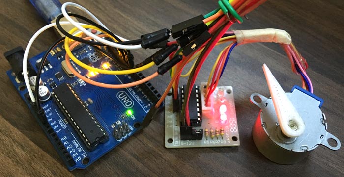
Material Required
- MATLAB installed Laptop (Preference: R2016a or above versions)
- Arduino UNO
- Stepper Motor (28BYJ-48, 5VDC)
- ULN2003 - Stepper motor driver
Circuit Diagram

Controlling Stepper Motor with MATLAB
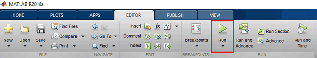
After setup the hardware according to circuit diagram, just click on the run button to run the edited code in .m file
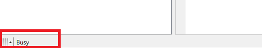
MATLAB may take few seconds to respond, do not click on any GUI buttons until MATLAB is showing busy message in the lower side of left corner as shown below,
When everything is ready, click on clockwise or anticlockwise button to rotate the motor. As we are using toggle button, the stepper motor will continuously move in clockwise direction until we press the button again. Similarly, by pressing the anti-clockwise toggle button, motor starts rotating in anti-clockwise direction until we press the button again.
function varargout = untitled1(varargin)
gui_Singleton = 1;
gui_State = struct('gui_Name', mfilename, ...
'gui_Singleton', gui_Singleton, ...
'gui_OpeningFcn', @untitled1_OpeningFcn, ...
'gui_OutputFcn', @untitled1_OutputFcn, ...
'gui_LayoutFcn', [] , ...
'gui_Callback', []);
if nargin && ischar(varargin{1})
gui_State.gui_Callback = str2func(varargin{1});
end
if nargout
[varargout{1:nargout}] = gui_mainfcn(gui_State, varargin{:});
else
gui_mainfcn(gui_State, varargin{:});
end
function untitled1_OpeningFcn(hObject, eventdata, handles, varargin)
function varargout = untitled1_OutputFcn(hObject, eventdata, handles)
varargout{1} = handles.output;
clear all;
global a;
a = arduino();
function clockwise_Callback(hObject, eventdata, handles)
while get(hObject,'Value')
global a;
writeDigitalPin(a, 'D8', 1);
writeDigitalPin(a, 'D9', 0);
writeDigitalPin(a, 'D10', 0);
writeDigitalPin(a, 'D11', 1);
pause(0.0002);
writeDigitalPin(a, 'D8', 0);
writeDigitalPin(a, 'D9', 0);
writeDigitalPin(a, 'D10', 1);
writeDigitalPin(a, 'D11', 1);
pause(0.0002);
writeDigitalPin(a, 'D8', 0);
writeDigitalPin(a, 'D9', 1);
writeDigitalPin(a, 'D10', 1);
writeDigitalPin(a, 'D11', 0);
pause(0.0002);
writeDigitalPin(a, 'D8', 1);
writeDigitalPin(a, 'D9', 1);
writeDigitalPin(a, 'D10', 0);
writeDigitalPin(a, 'D11', 0);
pause(0.0002);
end
function anticlockwise_Callback(hObject, eventdata, handles)
while get(hObject,'Value')
global a;
writeDigitalPin(a, 'D8', 1);
writeDigitalPin(a, 'D9', 1);
writeDigitalPin(a, 'D10', 0);
writeDigitalPin(a, 'D11', 0);
pause(0.0002);
writeDigitalPin(a, 'D8', 0);
writeDigitalPin(a, 'D9', 1);
writeDigitalPin(a, 'D10', 1);
writeDigitalPin(a, 'D11', 0);
pause(0.0002);
writeDigitalPin(a, 'D8', 0);
writeDigitalPin(a, 'D9', 0);
writeDigitalPin(a, 'D10', 1);
writeDigitalPin(a, 'D11', 1);
pause(0.0002);
writeDigitalPin(a, 'D8', 1);
writeDigitalPin(a, 'D9', 0);
writeDigitalPin(a, 'D10', 0);
writeDigitalPin(a, 'D11', 1);
pause(0.0002);
end
