

We have mostly covered all the Basic Components interfacing with Raspberry Pi in our Raspberry Pi Tutorial Series. We have covered all the Tutorials in simple and detailed manner, so that anyone, whether he has worked with Raspberry Pi or not, can learn from this Series easily. And after going through all the tutorials you will be able to build some High Level projects using Raspberry Pi.
So here we are designing first application based on the previous tutorials. The first basic application is a Reading Room Temperature by Raspberry Pi. And you can monitor the Readings on computer.
As discussed in previous tutorials, there are no ADC channels provided internally in Raspberry Pi. So if we want to interface any analog sensors we need an ADC conversion unit. And in one of our tutorials we have Interfaced ADC0804 chip to Raspberry Pi to read an analog value. So go through it before building this Room Temperature Thermometer.
ADC0804 and Raspberry Pi:
ADC0804 is a chip designed to convert analog signal in to 8 bit digital data. This chip is one of the popular series of ADC. It’s an 8bit conversion unit, so we have values or 0 to 255 values. The resolution of this chip changes based on the reference voltage we choose, we will talk more about it later. Below is the Pinout of ADC0804:
Now another important thing here is, the ADC0804 operates at 5V and so it provides output in 5V logic signal. In 8 pin output (representing 8bits), every pin provides +5V output to represent logic’1’. So the problem is the PI logic is of +3.3v, so you cannot give +5V logic to the +3.3V GPIO pin of PI. If you give +5V to any GPIO pin of PI, the board gets damaged.
So to step-down logic level from +5V, we will be using voltage divider circuit. We have discussed Voltage Divider Circuit previously look into it for further clarification. What we will do is, we use two resistors to divide +5V logic into 2*2.5V logics. So after division we will give +2.5v logic to PI. So, whenever logic ‘1’ is presented by ADC0804 we will see +2.5V at the PI GPIO Pin, instead of +5V.
LM35 Temperature Sensor:
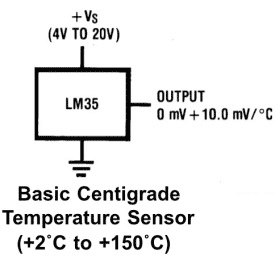
Now for Reading Temperature of Room, we need a sensor. Here we are going to use LM35 Temperature Sensor. Temperature is usually measured in “Centigrade” or “Fahrenheit”. “LM35” sensor provides output in degree Centigrade.
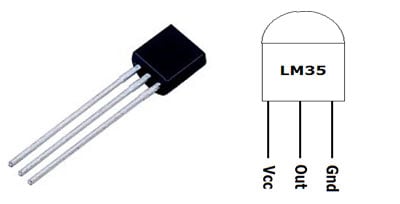
As shown in figure, LM35 is a three pin transistor like device. The pins are numbered as,
PIN1= Vcc - Power (Connected to +5V)
PIN2= Signal or Output (connected to ADC chip)
PIN3 = Ground (Connected to ground)
This sensor provides variable voltage at the output, based on temperature. For every +1 centigrade rise in temperature there will be +10mV higher voltage at the output pin. So if the temperature is 0◦ centigrade the output of sensor will be 0V, if the temperature is 10◦ centigrade the output of sensor will be +100mV, if the temperature is 25◦ centigrade the output of sensor will be +250mV.
Components Required:
Here we are using Raspberry Pi 2 Model B with Raspbian Jessie OS. All the basic Hardware and Software requirements are previously discussed, you can look it up in the Raspberry Pi Introduction, other than that we need:
- Connecting pins
- 1KΩresistor (17 pieces)
- 10K pot
- 0.1µF capacitor
- 100µF capacitor
- 1000µF capacitor
- ADC0804 IC
- LM35 Temperature Sensor
- Bread Board
Circuit and Working Explanation:
The connections which are done for Connecting Raspberry to ADC0804 and LM35, are shown in the circuit diagram below.

The LM35 output has lot of voltage fluctuations; so a 100uF capacitor is used to smooth out the output, as shown in the figure.
The ADC always have lots of noise, this noise can greatly affect the performance, so we use 0.1uF capacitor for Noise Filtration. Without this there will be lot of fluctuations at output.
The chip works on RC (Resistor-Capacitor) oscillator clock. As shown in circuit diagram, C2 and R20 form a Clock. The important thing to remember here is the capacitor C2 can be changed to a lower value for higher rate of ADC conversion. However with higher speed there will be decrease in accuracy. So if the application requires higher accuracy, choose the capacitor with higher value and for higher speed choose the capacitor with lower value.
As told earlier the LM35 provides +10mV for every centigrade. The maximum temperature that can be measured by the LM35 is 150º centigrade. So we will have a maximum of 1.5V at the LM35 output terminal. But the default reference voltage of ADC0804 is +5V. So if we use that reference value, the resolution of the output will be low because we would be using a maximum of (5/1.5) 34% of digital output range.
Luckily the ADC0804 has an adjustable Vref pin (PIN9) as shown it its Pin Diagram above. So we will set the Vref of the chip to +2V. To set Vref +2V, we need to provide a voltage of +1V (VREF/2) at PIN9. Here we are using 10K pot to adjust the voltage at PIN9 to +1V. Use the voltmeter to get the accurate voltage.
We have previously used LM35 Temperature Sensor to Read the Room temperature with Arduino and with AVR Microcontroller. Also check Humidity and Temperature Measurement using Arduino
Programming Explanation:
Once everything is connected as per the circuit diagram, we can turn ON the PI to write the program in PYHTON.
We will talk about few commands which we are going to use in PYHTON program,
We are going to import GPIO file from library, below function enables us to program GPIO pins of PI. We are also renaming “GPIO” to “IO”, so in the program whenever we want to refer to GPIO pins we will use the word ‘IO’.
import RPi.GPIO as IO
Sometimes, when the GPIO pins, which we are trying to use, might be doing some other functions. In that case, we will receive warnings while executing the program. Below command tells the PI to ignore the warnings and proceed with the program.
IO.setwarnings(False)
We can refer the GPIO pins of PI, either by pin number on board or by their function number. Like ‘PIN 29’ on the board is ‘GPIO5’. So we tell here either we are going to represent the pin here by ‘29’ or ‘5’.
IO.setmode (IO.BCM)
We are setting 8 pins as input pins. We will detect 8 bit of ADC data by these pins.
IO.setup(4,IO.IN)
IO.setup(17,IO.IN)
IO.setup(27,IO.IN)
IO.setup(22,IO.IN)
IO.setup(5,IO.IN)
IO.setup(6,IO.IN)
IO.setup(13,IO.IN)
IO.setup(19,IO.IN)
In case the condition in the braces is true, the statements inside the loop will be executed once. So if the GPIO pin 19 goes high, then the statements inside the IF loop will be executed once. If the GPIO pin 19 does not goes high, then the statements inside the IF loop will not be executed.
if(IO.input(19) == True):
Below command is used as forever loop, with this command the statements inside this loop will be executed continuously.
While 1:
Further Explanation of Code is given in Code Section Below.
After writing the program it’s time to execute it. Before executing program, lets talks what is happening in the circuit as a Summary. First LM35 sensor detects the room temperature and provides an analog voltage at its output. This variable voltage represents the temperature linearly with +10mV per ºC. This signal is fed to ADC0804 chip, this chip converts the Analog value to digital value with 255/200=1.275 count per10mv or 1.275count for 1degree. This count is taken in by the PI GPIO. The program converts the count to temperature value and displays it on the screen. The typical temperature read by PI is shown below,
Hence we this Raspberry Pi temperature monitor.
Complete Project Code
#working
import RPi.GPIO as IO            # calling for header file which helps us use GPIO’s of PI
import time                              # calling for time to provide delays in program
import sys
IO.setwarnings(False)            # do not show any warnings
x=1
b0 =0                                       # integer for storing the delay multiple
b1 =0
b2 =0
b3 =0
b4 =0
b5 =0
b6 =0
b7 =0
IO.setmode (IO.BCM)                # programming the GPIO by BCM pin numbers. (like PIN29 as‘GPIO5’)
IO.setup(4,IO.IN)                        # initialize GPIO Pins as input
IO.setup(17,IO.IN)
IO.setup(27,IO.IN)
IO.setup(22,IO.IN)
IO.setup(5,IO.IN)
IO.setup(6,IO.IN)
IO.setup(13,IO.IN)
IO.setup(19,IO.IN)
while 1:                                              # execute loop forever
    if (IO.input(19) == True):
        time.sleep(0.001)
        if (IO.input(19) == True):
            b7=1                                     # if pin19 is high bit7 is true
    if (IO.input(13) == True):
        time.sleep(0.001)
        if (IO.input(13) == True):
            b6=1                                     # if pin13 is high bit6 is true
    if (IO.input(6) == True):
        time.sleep(0.001)
        if (IO.input(6) == True):
            b5=1                                    # if pin6 is high bit5 is true
    if (IO.input(5) == True):
        time.sleep(0.001)
        if (IO.input(5) == True):
            b4=1                                   # if pin5 is high bit4 is true
    if (IO.input(22) == True):
        time.sleep(0.001)
        if (IO.input(22) == True):
            b3=1                                  # if pin22 is high bit3 is true
    if (IO.input(27) == True):
        time.sleep(0.001)
        if (IO.input(27) == True):
            b2=1                                 # if pin27 is high bit2 is true
    if (IO.input(17) == True):
        time.sleep(0.001)
        if (IO.input(17) == True):
            b1=1                                  # if pin17 is high bit1 is true
    if (IO.input(4) == True):
        time.sleep(0.001)
        if (IO.input(4) == True):
            b0=1                                      # if pin4 is high bit0 is true

    x = (1*b0)+(2*b1)                        # representing the bit values from LSB to MSB
    x = x+(4*b2)+(8*b3)
    x = x+(16*b4)+(32*b5)
    x = x+(64*b6)+(128*b7)
    x = x/1.275
    #temp=100,ref=2000mv,read=255/200=1.275countper10mv or 1.275count for 1degree
    print ( x)                                              # print the ADC value
    b0=b1=b2=b3=b4=b5=b6=b7=0      # reset the values
    time.sleep(0.01)                                 # wait for 10ms

can i use Raspberry pi 3 for the same configuration?