

When it comes to giving your projects wireless capabilities, the 433Mhz ASK Hybrid Transmitter and receiver is a common choice among engineers, developers, and hobbyists because of Its Low Price, easy to use libraries and its community support. We have also built few projects like RF controlled Home Automation and Wireless Doorbell using this 433MHz RF module. But often-times an ASK Hybrid Transmitter and receiver is just not enough, it's low range and one-way communication nature makes it unsuitable for many applications
To solve this ever-occurring problem, the developers at HopeRF devised a cool new RF module called RFM69HCW. In this tutorial, we will learn about the RFM69HCW RF module and its advantages. First, we will make Home made PCB for RFM69HCW and then interface RFM69HCW with Arduino to check its working so that you can use it in projects of your choice. So, let’s get started.
RFM69HCW RF Module
The RFM69HCW is a cheap easy to use radio module that operates in the unlicensed ISM (Industry, Science and Medicine) band similar to the nRF24L01 RF Module that we have used in previous projects. It can be used to communicate between two modules or can be configured as a Mesh Network to communicate among hundreds of modules that makes it a perfect choice for building inexpensive short-range wireless networks for sensors used in home automation and other data acquisition projects.
Features of RFM69HCW:
- +20 dBm - 100 mW Power Output Capability
- High Sensitivity: down to -120 dBm at 1.2 kbps
- Low current: Rx = 16 mA, 100nA register retention
- Programmable Pout: -18 to +20 dBm in 1dB steps
- Constant RF performance over a voltage range of module
- FSK, GFSK, MSK, GMSK and OOK modulations
- Built-in Bit Synchronizer performing Clock Recovery
- 115 dB+ Dynamic Range RSSI
- Automatic RF Sense with ultra-fast AFC
- Packet engine with CRC-16, AES-128, 66-byte FIFO Built-in temperature sensor
- High Link Budget
- Very Low Cost
RFM69HCW - Hardware Overview
Frequency
The RFM69HCW is devised to work in the ISM (Industry, Scientific and Medical) band, a set of unlicensed radio frequencies for low-power, short-range devices. Different frequencies are legal in different areas so that’s why the module has many different versions 315,433,868 and 915MHz. All major RF communication parameters are programmable and most of them can be dynamically set, also the RFM69HCW offers the unique advantage of programmable narrow-band and wide-band communication modes.
Note: Because of its comparatively low power and short-range, implementation of this module in a small project is not going to be an issue, but if you are thinking about making a product out of it be sure you are using the correct frequency for your location.
Range
To understand the range better we have to deal with quite a complicated topic called the RF Link Budget. So, what is this link budget and why it is so important? The link budget is like every other budget, something you have at the beginning and which you spend over time if your budget is used up you cannot spend more.

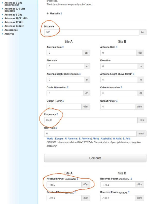
The link budget also has to do with a link or the connection between the sender and the receiver, it is filled up by the transmission power of the sender and the sensitivity of the receiver and it is calculated in decibels or dB it is also frequency-dependent. The link budget is deducted by all sorts of obstacles and noise between the sender and the receiver like distance cables walls trees buildings if the link budget is used up, the receiver only creates some noise at the output and we will not get any usable signal. According to the datasheet of the RFM69HCW, it has a link budget of 140 dB compared to 105 dB of the ASK Hybrid Transmitter but what does this means is this an important difference? Fortunately, we find Radio Link Budget Calculators online so Let's do some calculations to understand the topic better. First, let’s assume that we have a line of sight connection between sender and the receiver and everything is perfect as we know our Budget for RFM69HCW is 140 dB so let’s check the biggest theoretical distance we can communicate, we set everything to zero and the distance to 500KM, Frequency to 433MHz and we get a horizontal received-power of 139.2 dBm
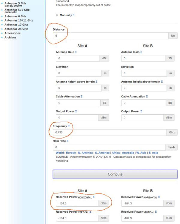
Now, I set everything to zero and the distance to 9KM Frequency to 433MHz and We get a horizontal received-power of 104.3 dBm
So with the above comparison, I think we can all agree that the RFM69 module is far better than the ASK Hybrid Transmitter and a receiver module.
The Antenna
Caution! Attaching an antenna to the module is mandatory because without it the module can be damaged by its own reflected power.
Creating an antenna is not as hard as it may sound. The simplest antenna can be made just from a single-stranded 22SWG wire. The wavelength of a frequency can be calculated by the formula v / f, where v is the speed of the transmission and f is the (average) transmission frequency. In the air, v is equal to c, the speed of light, which is 299.792.458 m/s. The wavelength for the 433 MHz band is thus 299.792.458 / 433.000.000 = 34,54 cm. Half of this is 17,27 cm and a quarter is 8,63 cm.
For the 433 MHz band the wavelength is 299.792.458 / 433.000.000 = 69,24 cm. Half of this is 34,62 cm and a quarter is 17,31 cm. So from the above formula, we can see the process of calculating the length of the antenna wire.
Power Requirement
The RFM69HCW has an operating voltage between 1.8V to 3.6V and can draw up to 130mA of current when it's transmitting. Below in the table, we can clearly see the power consumption of the module in different conditions
Warning: If your chosen Arduino uses 5V logic levels to communicate with the peripheral's hooking up the module directly to Arduino will damage the module
|
Symbol |
Description |
Conditions |
Min |
Typ |
Max |
Unit |
|
IDDSL |
Current in Sleep mode |
|
- |
0.1 |
1 |
uA |
|
IDDIDLE |
Current in Idle mode |
RC oscillator enabled |
- |
1.2 |
- |
uA |
|
IDDST |
Current in Standby Mode |
Crystal oscillator enabled |
- |
1.25 |
1.5 |
uA |
|
IDDFS |
current in Synthesizer mode |
|
- |
9 |
- |
uA |
|
IDDR |
current in Receive mode |
|
- |
16 |
- |
uA |
|
IDDT |
Supply current in Transmit mode with appropriate matching, stable across VDD range |
RFOP = +20 dBm, on PA_BOOST RFOP = +17 dBm, on PA_BOOST RFOP = +13 dBm, on RFIO pin RFOP = +10 dBm, on RFIO pin RFOP = 0 dBm, on RFIO pin RFOP = -1 dBm, on RFIO pin |
- - - - - - |
130 95 45 33 20 16 |
- - - - - - |
mA mA mA mA mAmA |
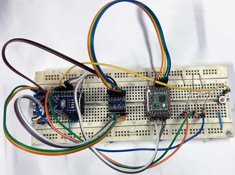
In this tutorial, we are going to use two Arduino Nano and two logic level converters to communicate with the module. We are using Arduino nano's because the built-in internal regulator can manage the peak current very efficiently. The Fritzing diagram in the hardware section below will explain it more clearly to you.
NOTE: If your power supply cannot provide 130mA of peak current your Arduino may reboot or worse the module can fail to communicate properly, in this situation a large value capacitor with low ESR can improve the situation
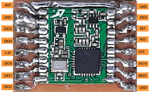
RFM69 Module Pinouts and Description
|
Label |
Function |
Function |
Label |
|
ANT |
RF signal output/input. |
Power Ground |
GND |
|
GND |
Antenna ground (same as power ground) |
Digital I/O, software configured |
DIO5 |
|
DIO3 |
Digital I/O, software configured |
Reset trigger input |
RST |
|
DIO4 |
Digital I/O, software configured |
SPI Chip select input |
NSS |
|
3.3V |
3.3V Supply (at least 130 mA) |
SPI Clock input |
SCK |
|
DIO0 |
Digital I/O, software configured |
SPI Data input |
MOSI |
|
DIO1 |
Digital I/O, software configured |
SPI Data output |
MISO |
|
DIO2 |
Digital I/O, software configured |
Power Ground |
GND |
Preparing Custom Development Board
When I bought the module it did not come with a breadboard compatible breakout board so we've decided to make one myself. If you might have to do the same then just follow the steps. Also, note that it is not mandatory to follow these steps, you can simply solder wires to the RF module and connect them to breadboard and it would still work. I am following this procedure only to get a stable and rugged set-up.
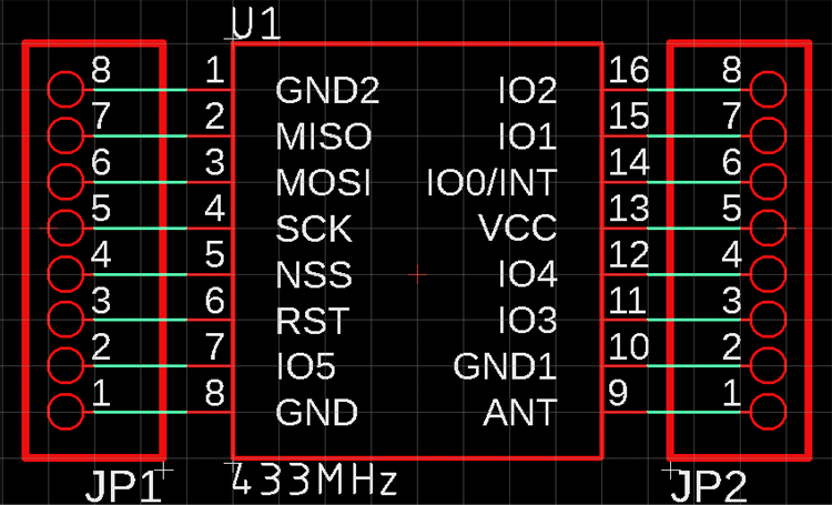
Step 1: Prepare the schematics for RFM69HCW module
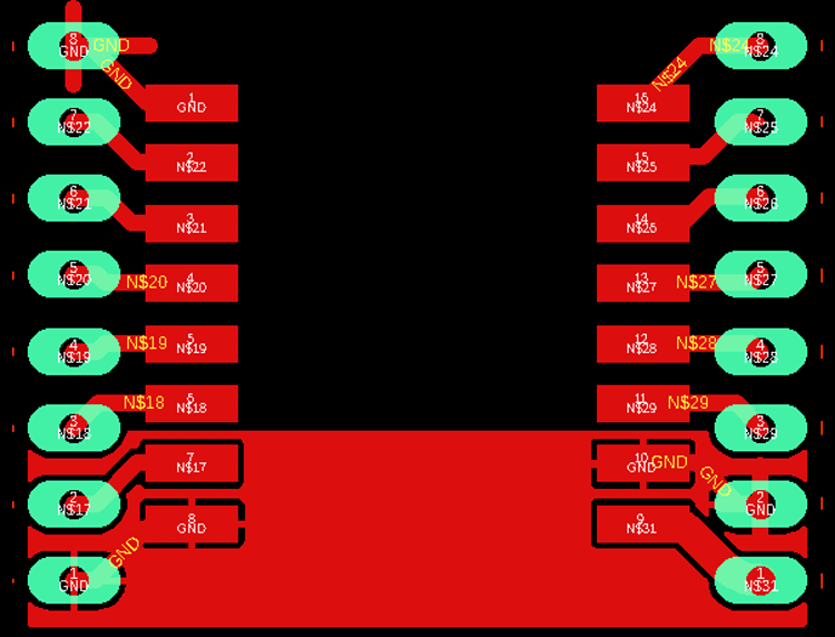
Step 2: Make the board layout on any PCB design software of your choice
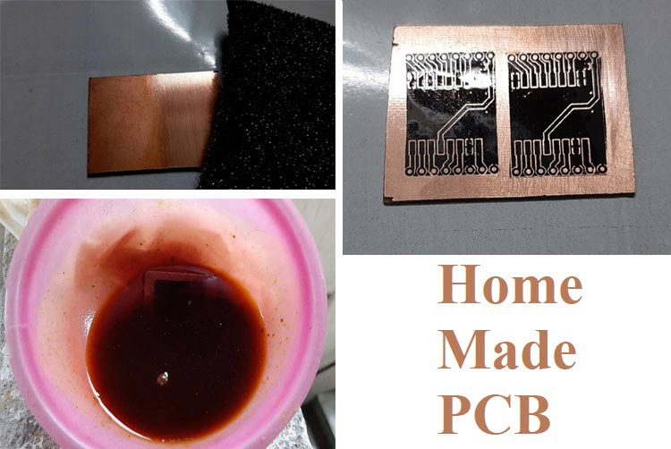
Step 3: Prepare a PCB for it, I am following this Home Made PCB tutorial. I printed the footprint on a copper board and dropped it in the etching solution
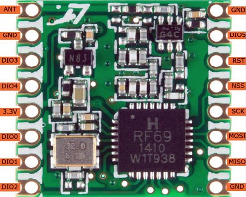
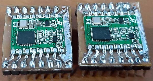
Step 4: Follow the procedure for both the boards and solder your module to the footprint. After soldering both my modules look like this below
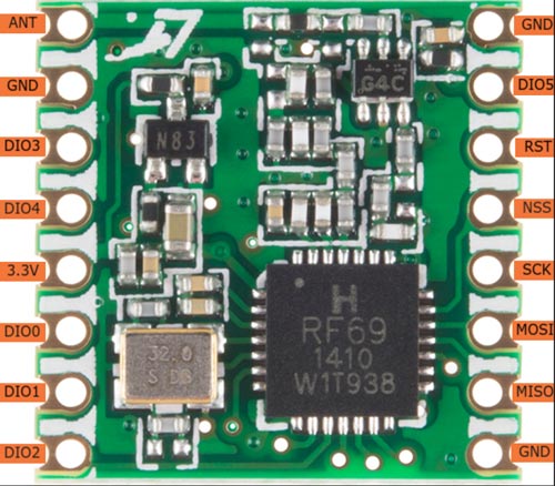
The pinout of RFM69HCW RF Module is given in the below figure
Materials Required
Here's the list of things you will need to communicate with the module
- Two RFM69HCW modules (with matching frequencies):
- 434 MHz (WRL-12823)
- Two Arduino (I am using Arduino NANO)
- Two logic level converters
- Two breakout boards (I am using a custom made breakout board)
- A push-button
- Four LED’s
- One 4.7K resistor four 220Ohms resistor
- Jumper wires
- Enameled copper wire (22AWG), to make the antenna.
- And finally soldering(if u already haven't done that)
Hardware connection
In this tutorial we are using Arduino nano which uses 5 volt logic but the RFM69HCW module uses 3.3 volt logic levels as you can clearly see in the above table so to properly communicate between two devices a logic level converter is mandatory, in the fritzing diagram below we have shown you how to hook up the Arduino nano to the RFM69 module.
Fritzing Diagram Sender Node

Connection Table Sender Node
|
Arduino Pin |
RFM69HCW Pin |
I/O Pins |
|
D2 |
DIO0 |
- |
|
D3 |
- |
TAC_SWITCH |
|
D4 |
- |
LED_GREEN |
|
D5 |
- |
LED_RED |
|
D9 |
- |
LED_BLUE |
|
D10 |
NSS |
- |
|
D11 |
MOSI |
- |
|
D12 |
MISO |
- |
|
D13 |
SCK |
- |
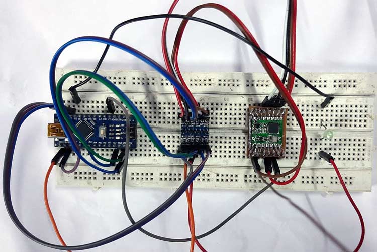
Fritzing Diagram Receiver Node

Connection Table Receiver Node
|
Arduino Pin |
RFM69HCW Pin |
I/O Pins |
|
D2 |
DIO0 |
- |
|
D9 |
- |
LED |
|
D10 |
NSS |
- |
|
D11 |
MOSI |
- |
|
D12 |
MISO |
- |
|
D13 |
SCK |
- |
Running the Example Sketch
In this tutorial, we're going to set up two Arduino RFM69 nodes and get them to communicate with each other. In the section below we will know how to get the module up and running with the help of the RFM69 library which is written by Felix Rusu of LowPowerLab.
Importing The Library
Hopefully, you have done a bit of Arduino programming before and know how to install a library. If not take check the Importing a .zip Library section of this link
Plugging in the Nodes
Plug in the USB of the Sender Node to your PC, a new COM port number should be added to the Arduino IDE's "Tools/Port" list, pen it down, now plug in the Receiver node another COM port should appear in the Tools/Port list, also pen it down, with the help of the port number we will upload the sketch to the sender and the receiver node.
Opening two Arduino sessions
Open two Arduino IDE sessions by double-clicking the Arduino IDE icon after the first session loads up, it's mandatory to open two Arduino sessions because that's how you can open two Arduino serial monitor window and simultaneously monitor the output of two nodes
Opening the Example Code
Now when everything is set up we need to open the example code in both Arduino sessions to do so, goto
File > Examples > RFM6_LowPowerLab > Examples > TxRxBlinky
and click it to open it
Modifying the Example Code
- Near the top of the code, look for #define NETWORKID and change the value to 0. With this Id, all of your nodes can communicate with each other.
- Look for the #define FREQUENCY change this to match the board frequency(mine is 433_MHz).
- Look for the #define ENCRYPTKEY this is your 16-bit encryption key.
- Look for #define IS_RFM69HW_HCW, and uncomment it if you are using an RFM69_HCW module
- And finally, look for #define NODEID it should be set as a RECEIVER by default
Now upload the code to your Receiver Node that you have previously set up.
Time to modify the Sketch for the Sender Node
Now in the #define NODEID macro change it to SENDER and upload the code to your Sender Node.
That's it, if u have done everything correctly u have two complete working models ready to test.
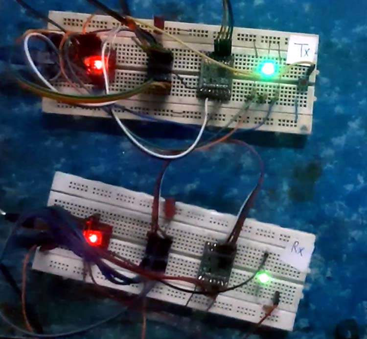
Working of the Example Sketch
After the successful upload of the Sketch you will observe the Red LED which is connected with the pin D4 of the Arduino lits up, now press the button in the Sender Node and you will observe that the Red LED turns off and the Green LED which is connected to the Pin D5 of the Arduino lights up as shown in the image below
You can also observe Button Pressed! text in the Serial monitor window as shown below
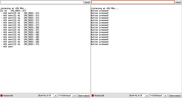
Now observe the Blue LED which is connected to the Pin D9 of the Sender Node, it will blink twice and in the Serial Monitor window of the Receive Node you will observe the following message and also the Blue LED which is connected to the D9 pin in the Receiver Node will lit up. If you see the above message in the Serial Monitor window of the receiver node and also if the LED lights up Congratulations! You have successfully communicated the RFM69 module with Arduino IDE. The complete working of this tutorial can also be found in the video given at the bottom of this page.
All in all these modules proves to be great for building weather stations, garage doors, wireless pump controller with indicator, drones, robots, your cat... the sky's the limit! Hope you understood the tutorial and enjoyed building something useful. If you have any questions please leave them in the comment section or use the forums for other technical queries.
RFM69HCW Transmitter Code:
// ***************************************************************************************
// Sample RFM69 sketch for Moteino to illustrate:
// - sending
// - receiving
// - automatic transmission control
// - button reading/interrupts
// ***************************************************************************************
// When you press the button on the SENDER Moteino, it will send a short message to the
// RECEIVER Moteino and wait for an ACK (acknowledgement that message was received) from
// the RECEIVER Moteino. If the ACK was received, the SENDER will blink the onboard LED
// a few times. The RECEIVER listens to a specific token, and it alternates the onboard LED
// state from HIGH to LOW or vice versa whenever this token is received.
// ***************************************************************************************
// Hardware setup:
// ***************************************************************************************
// On the sender, hook up a momentary tactile button to D3 like this:
// __-__
// __| |___
// GND ----> BTN ----> D3 (D11 on MoteinoMEGA)
// Load this sketch on the RECEIVER with NODEID=RECEIVER (adjust in config section below)
// Load this sketch on the SENDER with NODEID=SENDER (adjust in config section below)
// RFM69 library and code by Felix Rusu - felix@lowpowerlab.com
// Get libraries at: https://github.com/LowPowerLab/
// Make sure you adjust the settings in the configuration section below !!!
// **********************************************************************************
// Copyright Felix Rusu 2016, http://www.LowPowerLab.com/contact
// **********************************************************************************
// License
// **********************************************************************************
// This program is free software; you can redistribute it
// and/or modify it under the terms of the GNU General
// Public License as published by the Free Software
// Foundation; either version 3 of the License, or
// (at your option) any later version.
//
// This program is distributed in the hope that it will
// be useful, but WITHOUT ANY WARRANTY; without even the
// implied warranty of MERCHANTABILITY or FITNESS FOR A
// PARTICULAR PURPOSE. See the GNU General Public
// License for more details.
//
// Licence can be viewed at
// http://www.gnu.org/licenses/gpl-3.0.txt
//
// Please maintain this license information along with authorship
// and copyright notices in any redistribution of this code
// **********************************************************************************
#include <RFM69.h> //get it here: https://www.github.com/lowpowerlab/rfm69
#include <RFM69_ATC.h> //get it here: https://github.com/lowpowerlab/RFM69
#include <SPI.h> //included with Arduino IDE
#include <LowPower.h> //get library from: https://github.com/lowpowerlab/lowpower
//****************************************************************************************************************
//**** IMPORTANT RADIO SETTINGS - YOU MUST CHANGE/CONFIGURE TO MATCH YOUR HARDWARE TRANSCEIVER CONFIGURATION! ****
//****************************************************************************************************************
#define NETWORKID 100 //the same on all nodes that talk to each other
#define RECEIVER 1 //unique ID of the gateway/receiver
#define SENDER 2
#define NODEID RECEIVER //change to "SENDER" if this is the sender node (the one with the button)
//Match frequency to the hardware version of the radio on your Moteino (uncomment one):
#define FREQUENCY RF69_433MHZ
//#define FREQUENCY RF69_868MHZ
//#define FREQUENCY RF69_915MHZ
#define ENCRYPTKEY "sampleEncryptKey" //exactly the same 16 characters/bytes on all nodes!
#define IS_RFM69HW_HCW //uncomment only for RFM69HW/HCW! Leave out if you have RFM69W/CW!
//*****************************************************************************************************************************
#define ENABLE_ATC //comment out this line to disable AUTO TRANSMISSION CONTROL
#define ATC_RSSI -75
//*********************************************************************************************
#define SERIAL_BAUD 115200
#ifdef __AVR_ATmega1284P__
#define LED 15 // Moteino MEGAs have LEDs on D15
#define BUTTON_INT 1 //user button on interrupt 1 (D3)
#define BUTTON_PIN 11 //user button on interrupt 1 (D3)
#else
#define LED 9 // Moteinos have LEDs on D9
#define BUTTON_INT 1 //user button on interrupt 1 (D3)
#define BUTTON_PIN 3 //user button on interrupt 1 (D3)
#endif
#define LED_GREEN 4 //GREEN LED on the SENDER
#define LED_RED 5 //RED LED on the SENDER
#define RX_TOGGLE_PIN 7 //GPIO to toggle on the RECEIVER
#ifdef ENABLE_ATC
RFM69_ATC radio;
#else
RFM69 radio;
#endif
void setup() {
Serial.begin(SERIAL_BAUD);
radio.initialize(FREQUENCY,NODEID,NETWORKID);
#ifdef IS_RFM69HW_HCW
radio.setHighPower(); //must include this only for RFM69HW/HCW!
#endif
radio.encrypt(ENCRYPTKEY);
#ifdef ENABLE_ATC
radio.enableAutoPower(ATC_RSSI);
#endif
char buff[50];
sprintf(buff, "\nListening at %d Mhz...", FREQUENCY==RF69_433MHZ ? 433 : FREQUENCY==RF69_868MHZ ? 868 : 915);
Serial.println(buff);
Serial.flush();
pinMode(BUTTON_PIN, INPUT_PULLUP);
pinMode(LED, OUTPUT);
attachInterrupt(BUTTON_INT, handleButton, FALLING);
pinMode(LED_GREEN, OUTPUT);
pinMode(LED_RED, OUTPUT);
pinMode(RX_TOGGLE_PIN, OUTPUT);
digitalWrite(LED_GREEN, LOW);
digitalWrite(LED_RED, HIGH);
}
//******** THIS IS INTERRUPT BASED DEBOUNCING FOR BUTTON ATTACHED TO D3 (INTERRUPT 1)
#define FLAG_INTERRUPT 0x01
volatile int mainEventFlags = 0;
boolean buttonPressed = false;
void handleButton()
{
mainEventFlags |= FLAG_INTERRUPT;
}
byte LEDSTATE=LOW; //LOW=0
void loop() {
//******** THIS IS INTERRUPT BASED DEBOUNCING FOR BUTTON ATTACHED TO D3 (INTERRUPT 1)
if (mainEventFlags & FLAG_INTERRUPT)
{
LowPower.powerDown(SLEEP_120MS, ADC_OFF, BOD_ON);
mainEventFlags &= ~FLAG_INTERRUPT;
if (!digitalRead(BUTTON_PIN)) {
buttonPressed=true;
}
}
if (buttonPressed)
{
Serial.println("Button pressed!");
buttonPressed = false;
if(LEDSTATE==LOW)
{
LEDSTATE=HIGH;
digitalWrite(LED_GREEN, HIGH);
digitalWrite(LED_RED, LOW);
}
else
{
LEDSTATE=LOW;
digitalWrite(LED_GREEN, LOW);
digitalWrite(LED_RED, HIGH);
}
if (radio.sendWithRetry(RECEIVER, "Hi", 2)) //target node Id, message as string or byte array, message length
Blink(LED, 40, 3); //blink LED 3 times, 40ms between blinks
}
//check if something was received (could be an interrupt from the radio)
if (radio.receiveDone())
{
//print message received to serial
Serial.print('[');Serial.print(radio.SENDERID);Serial.print("] ");
Serial.print((char*)radio.DATA);
Serial.print(" [RX_RSSI:");Serial.print(radio.RSSI);Serial.print("]");
Serial.println();
//check if received message is 2 bytes long, and check if the message is specifically "Hi"
if (radio.DATALEN==2 && radio.DATA[0]=='H' && radio.DATA[1]=='i')
{
if(LEDSTATE==LOW)
LEDSTATE=HIGH;
else LEDSTATE=LOW;
digitalWrite(LED, LEDSTATE);
digitalWrite(RX_TOGGLE_PIN, LEDSTATE);
}
//check if sender wanted an ACK
if (radio.ACKRequested())
{
radio.sendACK();
Serial.print(" - ACK sent");
}
}
radio.receiveDone(); //put radio in RX mode
Serial.flush(); //make sure all serial data is clocked out before sleeping the MCU
LowPower.powerDown(SLEEP_8S, ADC_OFF, BOD_ON); //sleep Moteino in low power mode (to save battery)
}
void Blink(byte PIN, byte DELAY_MS, byte loops)
{
for (byte i=0; i<loops; i++)
{
digitalWrite(PIN,HIGH);
delay(DELAY_MS);
digitalWrite(PIN,LOW);
delay(DELAY_MS);
}
}
RFM69HCW Receiver Code:
// **********************************************************************************
#include <RFM69.h>
#include <RFM69_ATC.h>
#include <SPI.h>
#include <LowPower.h>
//****************************************************************************************************************
//**** IMPORTANT RADIO SETTINGS - YOU MUST CHANGE/CONFIGURE TO MATCH YOUR HARDWARE TRANSCEIVER CONFIGURATION! ****
//****************************************************************************************************************
#define NETWORKID 100 //the same on all nodes that talk to each other
#define RECEIVER 1 //unique ID of the gateway/receiver
#define SENDER 2
#define NODEID RECEIVER //change to "SENDER" if this is the sender node (the one with the button)
//Match frequency to the hardware version of the radio on your Moteino (uncomment one):
#define FREQUENCY RF69_433MHZ
//#define FREQUENCY RF69_868MHZ
//#define FREQUENCY RF69_915MHZ
#define ENCRYPTKEY "sampleEncryptKey" //exactly the same 16 characters/bytes on all nodes!
#define IS_RFM69HW_HCW //uncomment only for RFM69HW/HCW! Leave out if you have RFM69W/CW!
//*****************************************************************************************************************************
#define ENABLE_ATC //comment out this line to disable AUTO TRANSMISSION CONTROL
#define ATC_RSSI -75
//*********************************************************************************************
#define SERIAL_BAUD 115200
#ifdef __AVR_ATmega1284P__
#define LED 15 // Moteino MEGAs have LEDs on D15
#define BUTTON_INT 1 //user button on interrupt 1 (D3)
#define BUTTON_PIN 11 //user button on interrupt 1 (D3)
#else
#define LED 9 // Moteinos have LEDs on D9
#define BUTTON_INT 1 //user button on interrupt 1 (D3)
#define BUTTON_PIN 3 //user button on interrupt 1 (D3)
#endif
#define LED_GREEN 4 //GREEN LED on the SENDER
#define LED_RED 5 //RED LED on the SENDER
#define RX_TOGGLE_PIN 7 //GPIO to toggle on the RECEIVER
#ifdef ENABLE_ATC
RFM69_ATC radio;
#else
RFM69 radio;
#endif
void setup() {
Serial.begin(SERIAL_BAUD);
radio.initialize(FREQUENCY,NODEID,NETWORKID);
#ifdef IS_RFM69HW_HCW
radio.setHighPower(); //must include this only for RFM69HW/HCW!
#endif
radio.encrypt(ENCRYPTKEY);
#ifdef ENABLE_ATC
radio.enableAutoPower(ATC_RSSI);
#endif
char buff[50];
sprintf(buff, "\nListening at %d Mhz...", FREQUENCY==RF69_433MHZ ? 433 : FREQUENCY==RF69_868MHZ ? 868 : 915);
Serial.println(buff);
Serial.flush();
pinMode(BUTTON_PIN, INPUT_PULLUP);
pinMode(LED, OUTPUT);
attachInterrupt(BUTTON_INT, handleButton, FALLING);
pinMode(LED_GREEN, OUTPUT);
pinMode(LED_RED, OUTPUT);
pinMode(RX_TOGGLE_PIN, OUTPUT);
digitalWrite(LED_GREEN, LOW);
digitalWrite(LED_RED, HIGH);
}
//******** THIS IS INTERRUPT BASED DEBOUNCING FOR BUTTON ATTACHED TO D3 (INTERRUPT 1)
#define FLAG_INTERRUPT 0x01
volatile int mainEventFlags = 0;
boolean buttonPressed = false;
void handleButton()
{
mainEventFlags |= FLAG_INTERRUPT;
}
byte LEDSTATE=LOW; //LOW=0
void loop() {
//******** THIS IS INTERRUPT BASED DEBOUNCING FOR BUTTON ATTACHED TO D3 (INTERRUPT 1)
if (mainEventFlags & FLAG_INTERRUPT)
{
LowPower.powerDown(SLEEP_120MS, ADC_OFF, BOD_ON);
mainEventFlags &= ~FLAG_INTERRUPT;
if (!digitalRead(BUTTON_PIN)) {
buttonPressed=true;
}
}
if (buttonPressed)
{
Serial.println("Button pressed!");
buttonPressed = false;
if(LEDSTATE==LOW)
{
LEDSTATE=HIGH;
digitalWrite(LED_GREEN, HIGH);
digitalWrite(LED_RED, LOW);
}
else
{
LEDSTATE=LOW;
digitalWrite(LED_GREEN, LOW);
digitalWrite(LED_RED, HIGH);
}
if (radio.sendWithRetry(RECEIVER, "Hi", 2)) //target node Id, message as string or byte array, message length
Blink(LED, 40, 3); //blink LED 3 times, 40ms between blinks
}
//check if something was received (could be an interrupt from the radio)
if (radio.receiveDone())
{
//print message received to serial
Serial.print('[');Serial.print(radio.SENDERID);Serial.print("] ");
Serial.print((char*)radio.DATA);
Serial.print(" [RX_RSSI:");Serial.print(radio.RSSI);Serial.print("]");
Serial.println();
//check if received message is 2 bytes long, and check if the message is specifically "Hi"
if (radio.DATALEN==2 && radio.DATA[0]=='H' && radio.DATA[1]=='i')
{
if(LEDSTATE==LOW)
LEDSTATE=HIGH;
else LEDSTATE=LOW;
digitalWrite(LED, LEDSTATE);
digitalWrite(RX_TOGGLE_PIN, LEDSTATE);
}
//check if sender wanted an ACK
if (radio.ACKRequested())
{
radio.sendACK();
Serial.print(" - ACK sent");
}
}
radio.receiveDone(); //put radio in RX mode
Serial.flush(); //make sure all serial data is clocked out before sleeping the MCU
LowPower.powerDown(SLEEP_8S, ADC_OFF, BOD_ON); //sleep Moteino in low power mode (to save battery)
}
void Blink(byte PIN, byte DELAY_MS, byte loops)
{
for (byte i=0; i<loops; i++)
{
digitalWrite(PIN,HIGH);
delay(DELAY_MS);
digitalWrite(PIN,LOW);
delay(DELAY_MS);
}
}
