

SemLab Contactless Liquid Level Sense Module
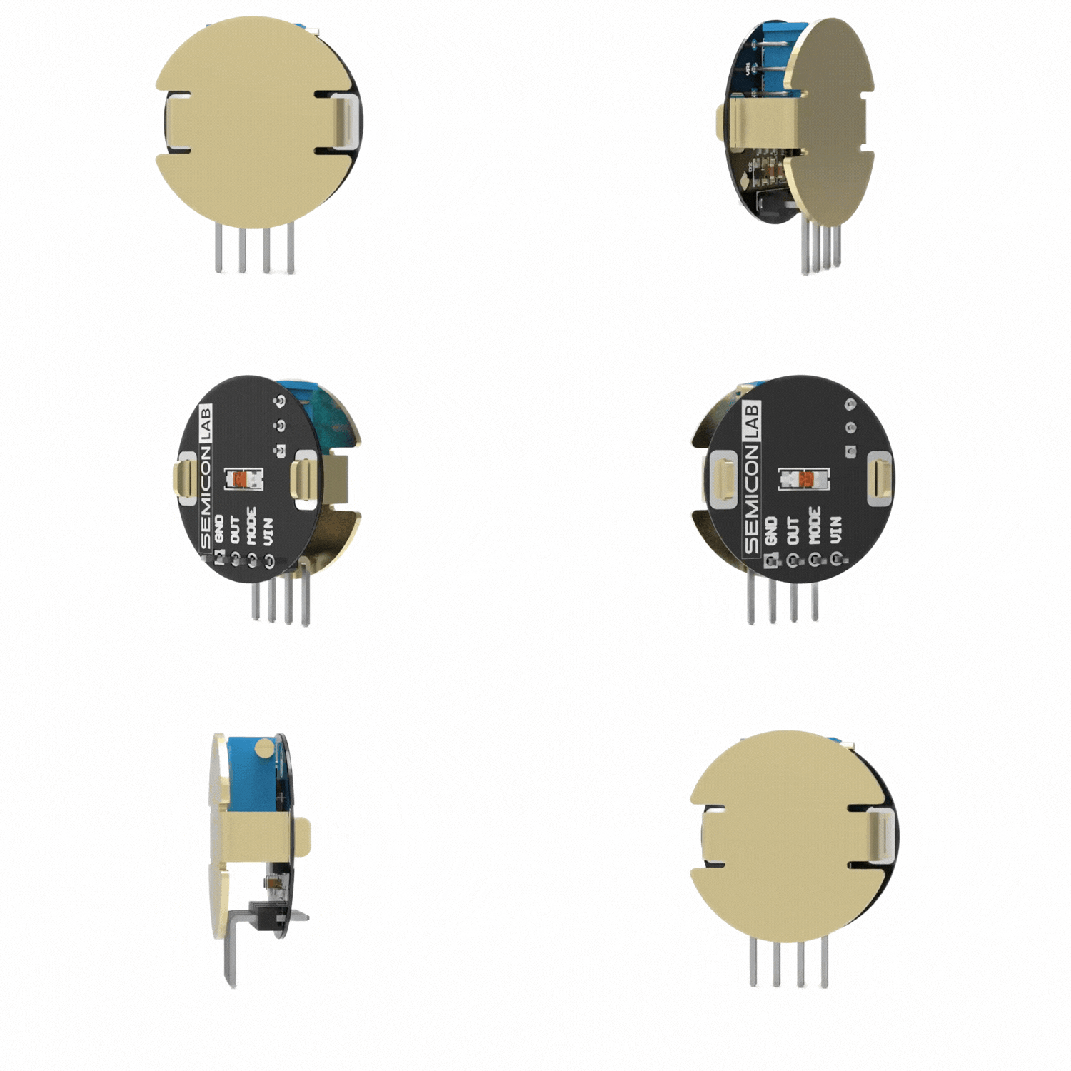
The SemLab Contactless Liquid Level Sense Module is an open-source, liquid level sensor designed for non-invasive fluid detection. By utilizing capacitive sensing, the sensor detects the presence of liquid inside a container or pipeline without making direct contact with the fluid. This non-contact design prevents sensor corrosion, contamination, and degradation caused by harsh chemical agents, strong acids, or alkalis, making it ideal for chemical, agricultural, and consumer IoT applications.
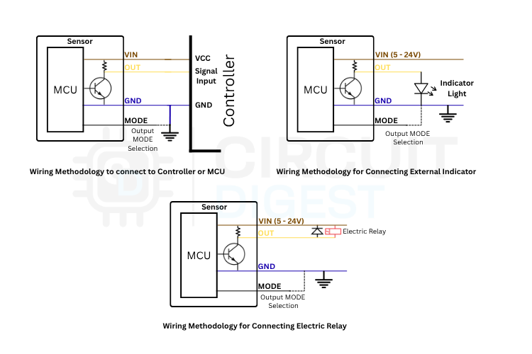
The module is shipped in a bare PCB style with pin headers attached, making it highly accessible for hobbyists to integrate into their own projects. Although it does not ship with physical waterproofing, the underlying electronics are capable of matching industrial-grade performance when paired with a protective physical enclosure, and the sensor can interface directly with downstream devices such as PLCs, relays, and microcontrollers(such as Arduino or ESP32).
Specifications
| Parameter | Details |
|---|---|
| Product Model | SemLab CLS-24BP |
| Core Microcontroller | WCH CH32V003F4U6 (32-bit RISC-V core @ 48 MHz, 16 KB Flash, 2 KB SRAM, QFN20) |
| Operating Voltage | DC 5V – 24V (Wide Range) |
| Current Consumption | ~5 mA (Standby) |
| Sensing Interface | Two-Pin Charge-Transfer (PC3 Excite / PC4 Sense) |
| Output Mode | Open-Collector Transistor Output (NPN or PNP selectable via MODE pin) |
| Output Drive Capacity | Up to 100 mA (suitable for small relays, PLCs, or logic inputs) |
| Response Time | ≤ 800 ms |
| Sensitivity Range | ≤ 20 mm (Container wall thickness) |
| Liquid Level Accuracy | ± 1.5 mm |
| Waterproof Rating | Bare PCB (IP00) / Enclosure dependent |
| Terminal Interface | 4-Pin Header |
Hardware Overview
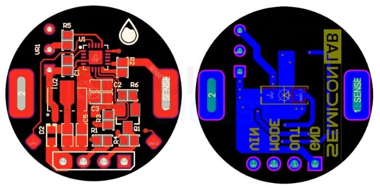
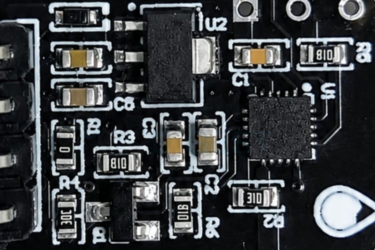
The hardware design of the SemLab Contactless Liquid Level Sense Module is structured around the WCH CH32V003F4U6 microcontroller, which manages the sensor inputs and drives the output state. Power regulation is handled by a Holtek HT7533-1 low-dropout (LDO) regulator (U2), which regulates an input voltage range of 5V to 24V down to a stable 3.3V system rail. A diode (D2) is placed in series with the VIN line to provide reverse-polarity protection.
For calibration, a 10kΩ trimpot (3296W) (VR1) is connected between the 3.3V rail and ground, acting as a voltage divider, its wiper is connected to the microcontroller’s ADC channel to set the sensitivity threshold. The excite pin (PC3) is connected to the sense pin (PC4) through a 1MΩ resistor (R2) to form the RC measurement path, with the sense pin routed to the probe pad.
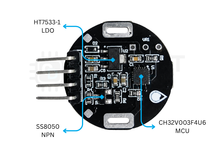
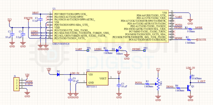
The output control circuit uses an SS8050 NPN transistor Q1 to drive the external load. The emitter of Q1 is connected directly to ground, while its collector is connected to the signal output pin OUT and pulled up to the input voltage (LDO_IN) through a 20kΩ resistor (R4). The base of Q1 is connected to the microcontroller’s PC2 pin through a 1kΩ current-limiting resistor (R6). When PC2 is driven high, Q1 turns on and pulls OUT to ground. When PC2 is driven low, Q1 turns off and OUT is pulled high by R4. An on-board LED (D1) is driven by PC1 through a 1kΩ resistor (R3) to provide a visual indication when liquid is detected.
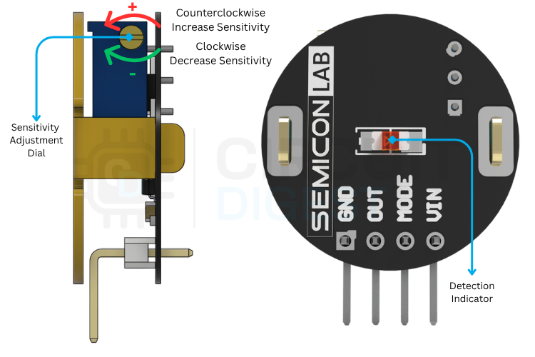
The module interfaces with external circuits through a 4-pin header (J1) labeled on the PCB silk screen.
| Header Pin | Silk Screen Name | Connection Destination |
|---|---|---|
| 1 | VIN | DC Power Supply Positive 5V to 24V supply rail |
| 2 | MODE | Output Mode Selection: Tie to GND for PNP Mode; Leave Floating for NPN Mode |
| 3 | OUT | Transistor Signal Output (Connect to PLC input, relay, or microcontroller) |
| 4 | GND | Power Supply Negative (GND) / System Ground (0V) |
Working Principle
Capacitive Liquid Level Sensing
Capacitive liquid level sensing is based on the principles of electrostatics. A capacitor is formed when two conducting electrodes are separated by an insulating dielectric material. In a contactless liquid level sensor, the sensor’s copper electrode acts as one plate of a virtual capacitor, the container wall acts as the dielectric, and the liquid itself (which is typically conductive or has a high dielectric constant) acts as the opposing plate or grounds the electric field. The capacitance (C) of a parallel-plate capacitor is given by the formula,

where εᵣ is the relative permittivity (dielectric constant) of the material between the plates, ε₀ is the vacuum permittivity, A is the area of the plates, and d is the distance between them. Air has a relative permittivity of approximately 1, while water has a very high relative permittivity of around 80. Consequently, when water or any aqueous liquid rises and comes into proximity with the sensor’s electrode through the container wall, the effective permittivity of the surrounding medium increases dramatically, which in turn causes a significant increase in the measured capacitance.
Capacitance Measurement
To measure this capacitance, the module utilizes a resistive-capacitive (RC) charge-transfer circuit formed by an excite pin, a sense pin, and a 1MΩ resistor. The time required to charge a capacitor to a certain voltage is proportional to the RC time constant (τ = R × C). When the container is empty, the capacitance at the sense pin is low, leading to a small time constant. When the excite pin is driven high, the voltage at the sense pin rises very rapidly. When liquid is present, the higher capacitance increases the time constant, causing the voltage at the sense pin to rise much slower. By triggering an analog-to-digital converter (ADC) measurement at a fixed, precise interval after the excitation signal begins, the microcontroller can capture the instantaneous voltage. A higher voltage corresponds to a low-capacitance dry state, whereas a lower voltage corresponds to a high-capacitance wet state.
Firmware Implementation
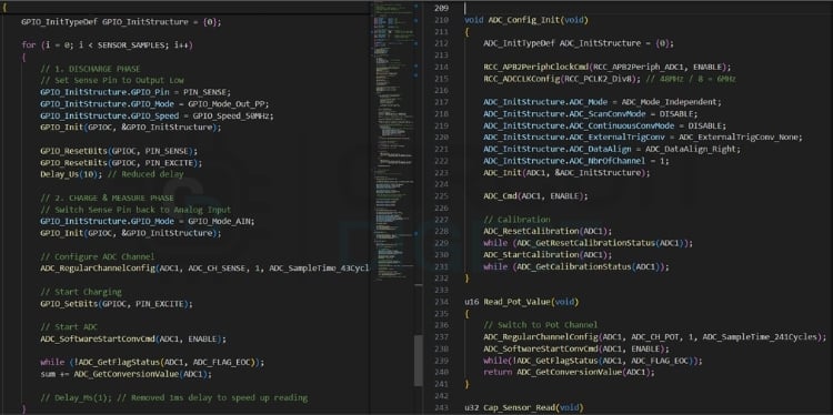
The firmware implements this physical measurement by executing a discharge and charge cycle. During the discharge phase, both the excite and sense pins are driven to ground to drain any stored charge on the probe. During the charge phase, the sense pin is reconfigured as an analog input, the excite pin is driven high, and the ADC conversion is immediately triggered. To filter out high-frequency noise, the microcontroller performs this cycle 500 times per reading and sums the ADC results. This oversampled sum is then mapped to a standardized scale from 0 to 1000 using calibration limits. To prevent output flickering near the transition point, an exponential moving average (EMA) filter is applied to smooth the mapped values, and a hysteresis buffer is used to ensure clean state transitions.
Mode Configuration (NPN vs. PNP)
The module supports NPN and PNP output emulation, allowing it to interface with various industrial and hobbyist controllers. The output mode is determined at startup by sensing the state of the MODE pin (PD1) which is connected to Pin 2 of the J1 header. The microcontroller uses an internal pull-up resistor on PD1. If the MODE pin is left floating, the microcontroller detects a high logic state and operates in NPN mode. If the MODE pin is tied to GND, the microcontroller detects a low logic state and operates in PNP mode.
In NPN mode, the output is active-low on liquid detection. When liquid is detected, PC2 is driven high, turning on transistor Q1 and pulling OUT to ground, which allows it to sink current from an external load. When no liquid is detected, PC2 is driven low, turning off Q1 and leaving OUT pulled high to Vin through R4.
In PNP mode, the output is active-high on liquid detection. When liquid is detected, PC2 is driven low, turning off transistor Q1 and allowing the 20kΩ resistor R4 to pull OUT high to Vin, which can source a small current to an external load. When no liquid is detected, PC2 is driven high, turning on Q1 and pulling OUT to ground.
| Mode | MODE Pin (J1 Pin 2) | PD1 State | PC2 Base Drive | Q1 Transistor State | OUT Level | External Behavior |
|---|---|---|---|---|---|---|
| NPN (Liquid) | Floating / High | High | High | ON | Low (GND) | Sinks current (Active-Low) |
| NPN (Dry) | Floating / High | High | Low | OFF | High (Vin) | Open-collector (Inactive) |
| PNP (Liquid) | Grounded | Low | Low | OFF | High (Vin) | Sources current (Active-High) |
| PNP (Dry) | Grounded | Low | High | ON | Low (GND) | Pulled to ground (Inactive) |
Installation Guide & Enclosure
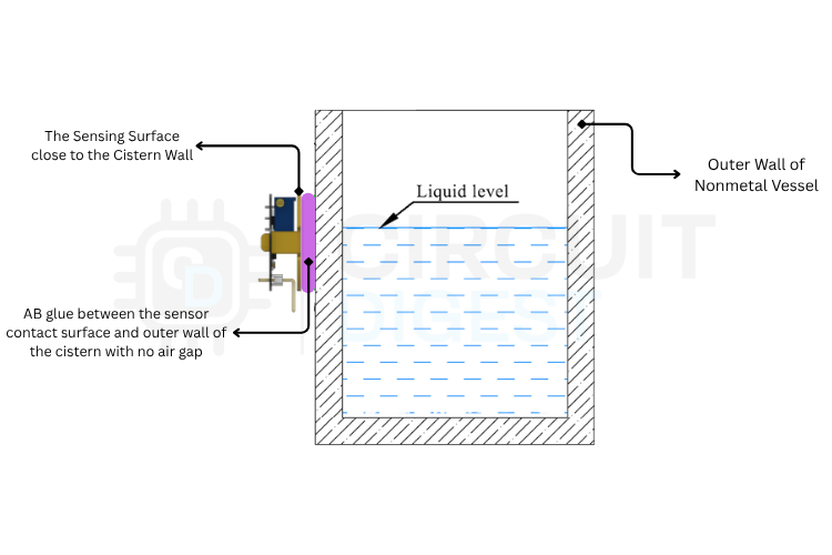
Since the module is sold in a bare PCB format, mounting and environmental protection must be handled during installation. For developers looking to deploy this sensor in environments requiring dust or water protection, a custom 3D-printable enclosure has been designed. Users can download the CAD files and 3D print their own cases.
For accurate detection, the active sensor face on the Brass Probe must make clean, tight contact with the outer container wall.
Insulating Material Containers (Glass, Plastic, Acrylic)
These containers are ideal for contactless sensing. Ensure the wall thickness does not exceed 20 mm. The container surface must be clean and flat. Avoid air bubbles or gaps in the adhesive. Use double-sided acrylic tape, epoxy, or AB glue to secure the PCB flat against the outer container wall. Ensure no metal brackets or parts are placed directly behind the sensor face.
Metal Conductive Containers (Stainless Steel, Copper)
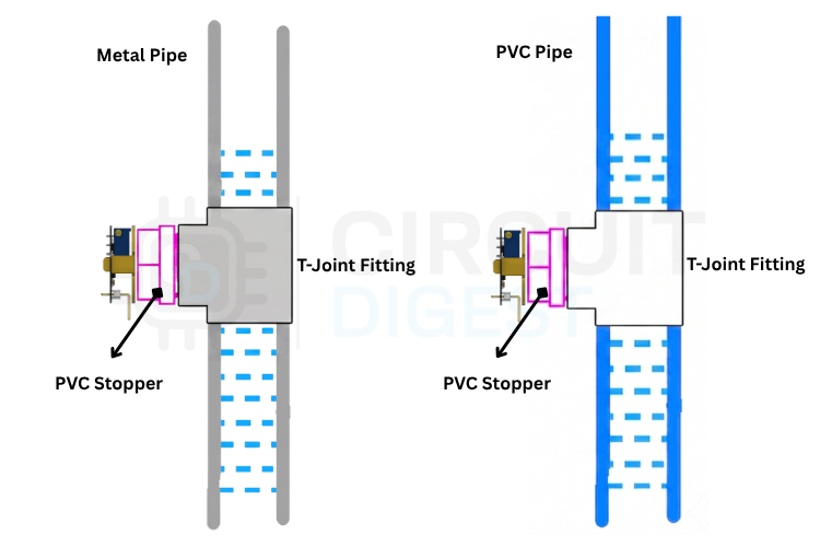
Capacitive sensors cannot penetrate conductive metal walls directly. Drill a hole in the metal container wall at the desired high or low trigger level. Insert a non-conductive rubber plug or sleeve into the opening. Securely paste the sensor onto the outer face of the rubber plug.
Water-Absorbing Containers (Ceramic, Concrete)
Materials that absorb water (such as brick, unglazed ceramics, or cement) act as weak electrical conductors when wet, causing false triggers. Use the same method as metal containers (drilling a hole and inserting a rubber plug) or mount the sensor on an external bypass pipe.
Sensitivity Calibration
The onboard potentiometer allows you to tune the detection threshold to match different container materials, wall thicknesses, and liquid types.
| Step | Condition | Adjustment | Acceptance Criteria |
|---|---|---|---|
| 1 | Mount the sensor in its final installation position with the sensing face exposed to air (dry condition). | The sensor is securely mounted in the final application geometry. | |
| 2 | Apply the rated supply voltage and observe the status LED. | LED state indicates the current switching condition. | |
| 3 | LED ON while the sensing face is dry (false dry-state detection). | Rotate the calibration potentiometer clockwise (CW) to decrease sensitivity (lower switching threshold) until the LED changes to OFF. | LED remains OFF under dry conditions. |
| 4 | Raise the liquid level until it fully covers the sensing area (sensor centerline). | The sensor is exposed to the target liquid. | |
| 5 | LED OFF while the sensing face is submerged (failure to detect liquid). | Rotate the calibration potentiometer counterclockwise (CCW) to increase sensitivity (raise switching threshold) until the LED changes to ON. | The LED remains ON when the sensing face is submerged. |
| 6 | Cycle the liquid level above and below the sensing area several times. | Readjust, if necessary, to obtain a stable switching point. | Sensor provides repeatable ON/OFF switching without false triggering or missed detection. |
Troubleshooting Guide
| Symptom | Probable Cause | Corrective Action |
|---|---|---|
| No response / LED remains permanently OFF | 1. Power cable disconnected. 2. Incorrect wiring polarity. 3. Operating voltage below 5V. 4. Sensitivity set too low. | 1. Verify brown (VCC) and blue (GND) connections. 2. Correct power supply polarity. 3. Check supply voltage with a multimeter. 4. Turn potentiometer CCW to increase sensitivity. |
| LED remains permanently ON (even when empty) | 1. Sensitivity set too high. 2. Metal brackets or parts too close to the sensor. 3. Liquid residue/scale coating the container inner wall. 4. Container wall absorbing water. | 1. Turn potentiometer CW to decrease sensitivity. 2. Relocate metal parts or brackets away from the sensor. 3. Clean the inside of the container. 4. For water-absorbing containers, use a rubber plug insert or external bypass pipe. |
| Output switches erratically (flickering) | 1. Sensor not pasted tightly to the wall (air gap). 2. Excessive ripple on the power supply rail. 3. Fluid turbulence/bubbles at the sensor height. | 1. Re-paste the sensor securely with AB glue, leaving no gaps. 2. Ensure power supply ripple is <=200mV. Install a decoupling capacitor if needed. 3. Position the sensor away from the container inlet or install a baffle. |
| Output logic is inverted | 1. MODE pin configured incorrectly. | 1. For NPN mode (load active on liquid), leave the MODE pin floating. For PNP mode (inverted output state), connect the MODE pin to GND. |
Open-Source Resources
All hardware designs, firmware source code, and 3D cad files for the SemLab Contactless Water Sense Module are open source and available on GitHub:
| Resource | Description | Link |
|---|---|---|
| Hardware Files | Schematic and PCB design files | GitHub Repository |
| Firmware Source Code | C source code and PlatformIO configuration | GitHub Repository |
| 3D Enclosure CAD | 3D printable STL and STEP enclosure files | GitHub Repository |
Where to Buy?
SemLab Contactless Liquid Level Sense Module is designed and maintained by CircuitDigest under the SemiconLab initiative. You can buy it from our distributors listed below:

Have any Questions?
Start a Discussion on: