India Automation Challenge 2021
OR


Hello there, Sometimes when we go out of our home for a few days. In this case, we cant give water to our favourite plants or we are busy with other works at that time we always forget to give water to our plants, most of the time we nearly forget about our plants in the mentioned cases It’s hard to keep our plants alive. Because most of the indoor plants require regular watering. Here I came with a simple solution. This is just awesome for lazy and busy people like me.
My solution is a Self-Watering Smart Pot. Any normal pot can be converted into a smart pot. With smart pot, we can make our plants healthy and happy
First, let’s see the features
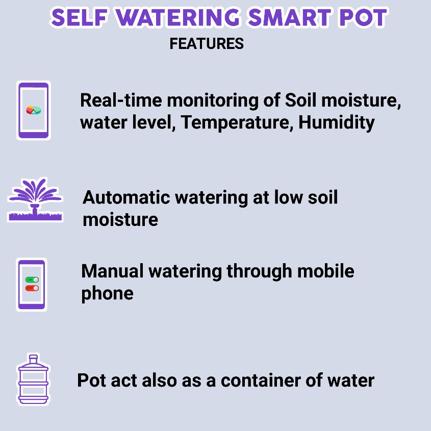
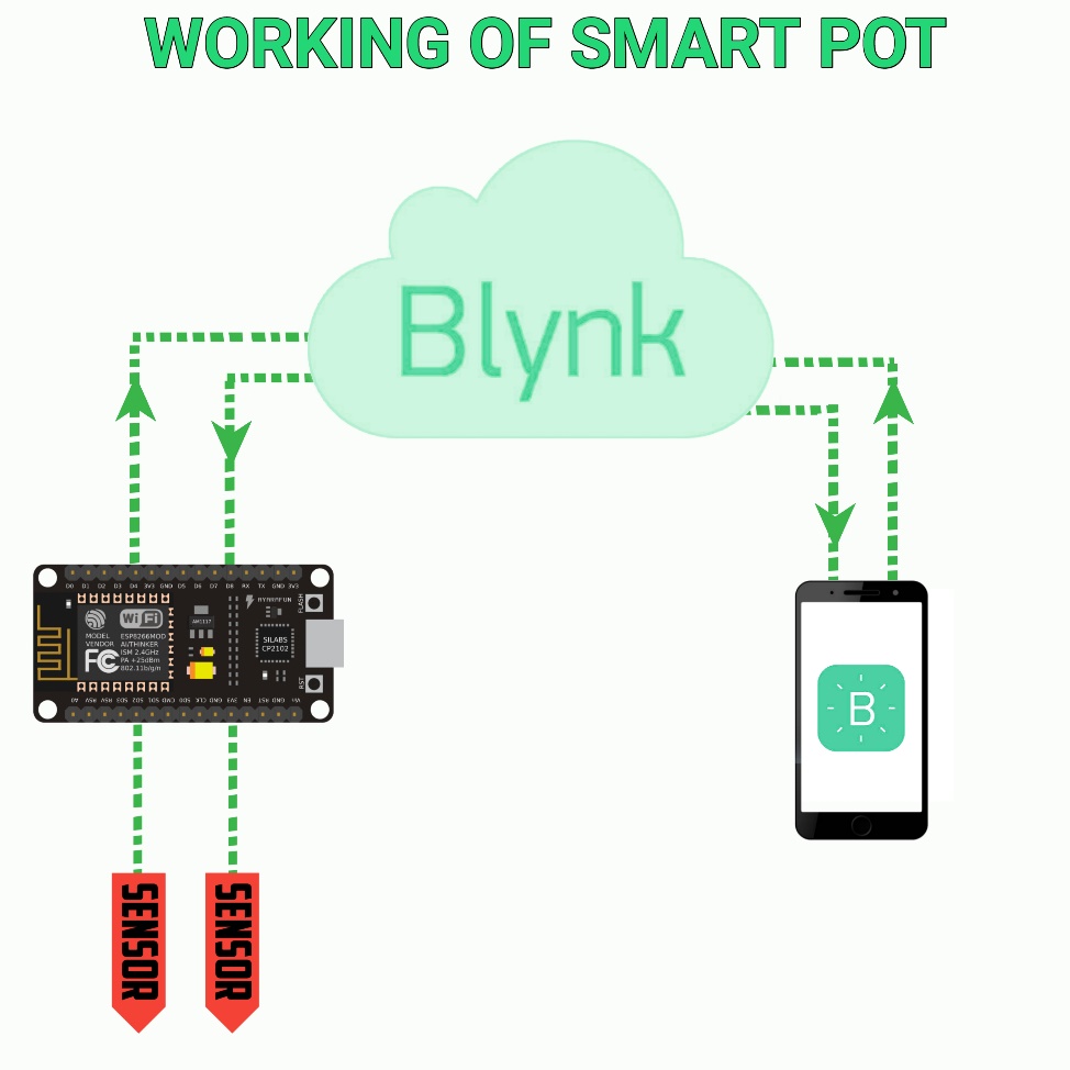
In an automatic plant watering system or the smart pot. we are using an esp microcontroller to control and sense everything. To measure the moisture in the soil and water level we are using a capacitive soil moisture sensor. with the help of the DHT11 sensor, we can measure the temperature and humidity. After reading these values we will send these values to the Blynk server (that’s why we are using esp microcontroller.) so that we can monitor the values using a mobile app. we can set the moisture level of the soil to turn on and off the attached water pump. We can also manually control this pump through the mobile application. So this is basically how a smart pot works.
we can use any microcontroller to build an automatic irrigation system. But to convert that to smart of course we need an internet connection, that is why I am going with the nodemcu. We can send or receive data using nodemcu. It has enough digital pins for our application.
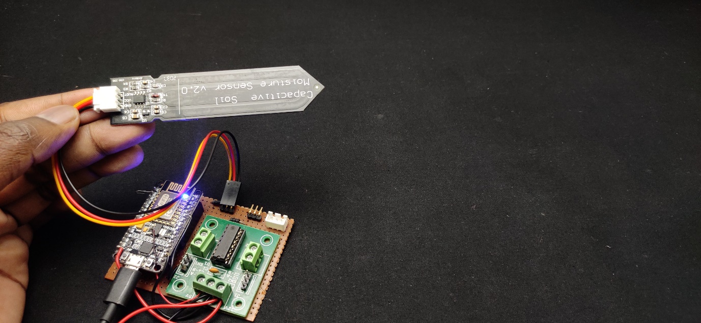
The job of a soil moisture sensor is to detect the water content of the soil. When it comes to this category of sensor we have two options that are Capacitive Soil Moisture Sensor and resistive moisture sensor. As the name indicates a Capacitive soil moisture sensor is based on capacitance changes. Compared with resistive sensors, capacitive sensors do not require direct exposure of the metal electrodes, which can significantly reduce the corrosion of the electrodes.
A capacitive moisture sensor works by measuring the changes in capacitance caused by the changes in the dielectric. As all, we know capacitance is proportional to the dielectric medium. The capacitance of the sensor is measured using a NE555 based circuit that produces a voltage proportional to the capacitance. The sensor has 3 pins VCC, GND and OUT. The output of a capacitive moisture sensor is an analogue value.
Also, we can use capacitive moisture as a water level sensor.
The DHT11 is a commonly used temperature and humidity sensor. The sensor comes with a dedicated NTC to measure temperature the output of the DHT sensor comes as serial data of temperature and humidity. The sensor is much accurate than other sensors and easy to interface with microcontrollers using the DHT library. The sensor can measure temperature from 0°C to 50°C and humidity from 20% to 90% with an accuracy of ±1°C and ±1%. So this is perfect for our application
We can’t directly connect the motor pump to the microcontroller because pumps will draw more current so leading to the destruction of the microcontroller. So to control the pump, I used the L293D IC module, I choose this IC because to decrease the size. And this IC is good for controlling small motors. You can also use a relay. This module is designed for controlling 2 motors. We need only one side.
In this section, I will explain all the details circuit diagram. The Nodemcu is the brain of this smart pot project.it reads the values of moisture sensors and DHT module then it sends that’s values to the Blynk server through a wifi connection. also, It controls the pump according to the moisture in the soil or with the app commands.
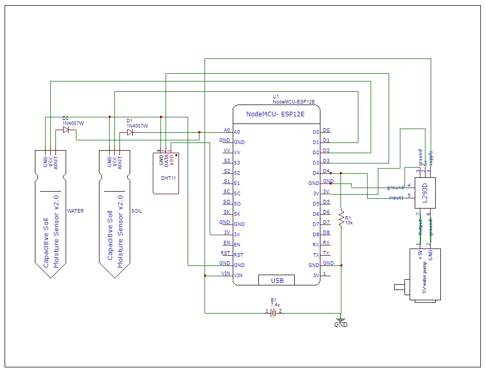
Unlike other development boards like Arduino, blue pill nodemcu has only one analogue pin. But we have two analogue moisture sensors! So how to read two analogue values using one analogue pin.? In the coming lines, I am explaining how to read multiple analogue values using only one pin.
in this circuit diagram, you can see I connected positive terminals of moisture sensors to digital pins 1 and 2 so we can turn off and on each sensor by turning on and off the digital pins. That is if the d1 is on that means sensor one is on. I connected a diode on the outputs of each sensor and the other side of the diode I connected to the analogue pin. Here comes the trick first we turn D1 (that is sensor 1) at the same time we read the analogue value. So we get the analogue value of the first sensor. Next, we turn off D1 and turn on the D2 and read the analogue value so we will get the analogue value of the second sensor. here diode is for isolation between the sensors. check the coding part too for better understanding.
I connected the DHT sensor to digital pin 3 and the motor driver/relay to D4. A 10k resistor is used to pull down the motor pin. This L293D motor driver module has three power pins ground, supply and a 5v. So I connected ground to ground supply to the positive side of the battery and 5v to the 3.3v pin of nodemcu. Also, remember to connect the enable to a 3.3v pin.
To power the circuit, I am using an external Battery. You can use any 6-12v battery(i recommend using an AC adapter for this). The battery is connected to the Vin and ground pins of Nodemcu and we can also connect the motor driver supply to this battery.
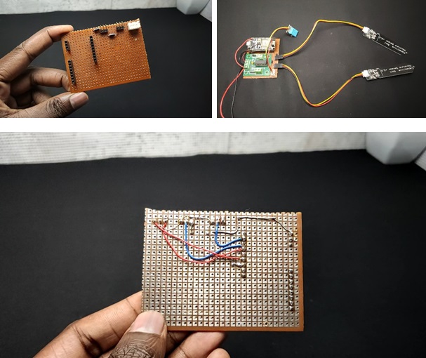
I started the circuit building by placing the female and male header pins for nodemcu and sensors. It's better to use header pins in circuits for easy troubleshooting. Also placed a 3 pin JST connector for the DHT sensor. Then I soldered all connectors to a common PCB. After that, I connected diodes to sensor connectors and completed the soldering job.
Then I placed the nodemcu on its socket and placed the motor driver near to the nodemcu and connected.
This is the pot that I bought from the local market. This is a combination of two pots. The black colour pot is comfortably fit inside the glazing green pot. And you can see from the image the green pot has some separating parts. That makes some space in between the two pots. We are going to use this space for storing the water.
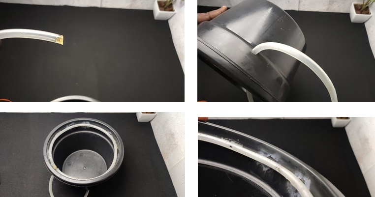
First I closed one side of the hose using hot glue and made a small hole (enough to fit the hose) on the black pot and inserted the hose through that hole. I made a circle using the hose inside the pot. I secured everything with glue. Then I made small holes on the hose using a soldering iron that's it.
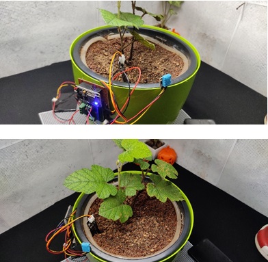
So this is the time to plant your favourite plant. So I filled the pot with sand and soil. Then I planted a berry plant. Now I connected the hose end to the motor pump. Remember to connect enough length wire to pump.
Now in the outer pot place the moisture level sensor on any side. Refer to images for better understanding. There is a line marking on the moisture sensor. So adjust the placing according to the water level. I fixed the moisture sensor using hot glue.
Finally step is to fill the water in the outer pot and then dip the pump on water. And finally, place the plant pot. (Refer to the video and images)
We have to calibrate the sensors before connecting. First, I connected one moisture sensor to the circuit. Then I admin/uploaded the calibration code. I used Arduino ide to admin/upload and edit the code. The following lines are about how the code works.
First I declared the pins, that is the analogue pin and sensor connected digital pin.
int Pin_D2 = 5;
In the setup section, I defined the modes of pins and started the serial communication at a baud rate of 9600.
void setup()
{
Serial.begin(9600);
pinMode(Pin_D2,OUTPUT);
pinMode(A0,INPUT);
}
In the loop section first i turned on the digital that i connected the sensor.We need only the output analog values so i used the analogread function and read the connected sensor values. Then I printed that values in the serial monitor.
void loop() {
digitalWrite(Pin_D2,HIGH);
int sensor = analogRead(A0);
Serial.println(sensor);
delay(1);
}
After admin/uploading this code to our nodemcu open the serial monitor and select the correct baud rate.
Hold the sensor in the air and note the analogue value. This value is our dry value. In my case, this is around 220.
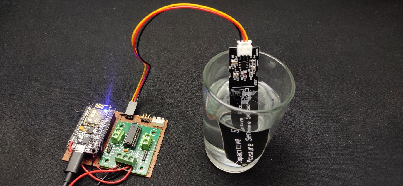
Take a glass of water and put the sensor in it remember to not dip the circuit. Again note the value and this is our wet value. In my case, this is around 600. So this value means the zero percentage and 100 % moisture
After getting these values connect the circuit to other sensors and the motor. place the soil moisture sensor in the soil.
I choose the blynk application because of these features
So first I downloaded the blynk application from the play store and installed it on my android phone. In the app First, you have to sign up with your email. After that, you will get an interface like this. Now click on a new project and give a name then choose the device as nodemcu. Then click create
Now you will get a pop-up message and that say an authentication token was sent to your email id.
Now click on the top right corner plus icon. Now select the gauge and again click on the gauge.
Now name the gauge as soil moisture, select pin as virtual pin V6 and in the range section change default values to 0-100. That’s it .this gauge will show the soil moisture reading of our sensor.
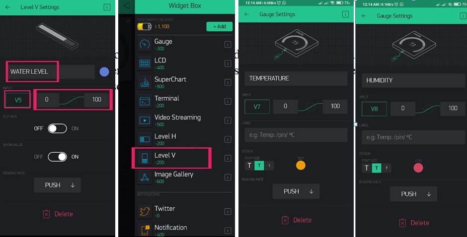
Same way to create 3 more gauges. The only change is in the virtual pins. You can change the colour and make it more attractive.
Now again click on the plus icon and add level v widget this widget is for showing the water level. So I named it as water level and I selected the virtual pin V5 also changes the range.
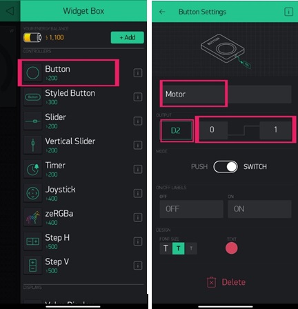
Finally, I added one more button widget and this is for controlling the water pump I this case I selected the digital pin 2 . so that’s all about the setting of the application
As we are now finished with the build process for our smart pot, we can move on to the programming part. For this project, we are using some libraries for easy programming. Complete code is given at the end of this tutorial. The code is very simple and easy to understand. The explanation of the code is as follows.
I am going to admin/upload code to a NodeMCU board, with Arduino IDE. So, we need to add the ESP Board package in the Arduino IDE. To do this, open your Arduino IDE, then open preference from the file menu. Paste the link given below and press OK.
http://arduino.esp8266.com/stable/package_esp8266com_index.json
Then go to tools->boards->board manager. Now search for ESP and install.
The code uses the ESP8266, Blynk, and DHT libraries. You can download the libraries from the given links. so first included these libraries and defined the blynk serial print function.
#define BLYNK_PRINT Serial
#include
#include
#include
Since we are using the Blynk Server, the token is necessary to communicate with the server. You can copy the token from the registered email id. Then I give the SSID and password of my hotspot. If you are going to replicate this project then just replace the characters with your token, SSID and password.
char auth[] = "EqF6GGkVt_kFgBJHIX0v32TrFcc_Wxy5";
char ssid[] = "edison science corner";
char pass[] = "eeeeeeee";
Then I defined all the required integers here I used integers for storing the read value and for storing the converted soil moisture. Then I declared the pins for the sensor and motor. Also, I defined the DHT pin and the sensor type. Finally, I gave the calibrated values in dry and wet integers.
int readD1;
int readD2;
int moisture_sensor1;
int moisture_sensor2;
int Pin_D1 = 5;
int Pin_D2 = 4;
int Pin_D4 = 2;
#define DHTPIN 0
#define DHTTYPE DHT11
const int dry = 600; // value for dry sensor
const int wet = 200; // value for wet sensor
DHT dht(DHTPIN, DHTTYPE);
BlynkTimer timer;
In the setup section first I started the serial communication this is just for better troubleshooting. Then I defined the modes of a pin here we have 3 outputs and one input. Also, I started the DHT and Blynk communication.
void setup()
{
Serial.begin(9600);
pinMode(Pin_D1,OUTPUT);
pinMode(Pin_D2,OUTPUT);
pinMode(Pin_D4,OUTPUT);
pinMode(A0,INPUT);
dht.begin();
timer.setInterval(1000L, sendSensor);
Blynk.begin(auth, ssid, pass);
}
In this void, I read the humidity and temperature of the DHT sensor and stored that float value in h hand t. Then using the Blynk.virtualWrite function I sent that values to the blynk server. Here V7 and V8 are just virtual pins.
void sendSensor()
{
float h = dht.readHumidity();
float t = dht.readTemperature();
Blynk.virtualWrite(V7, t);
Blynk.virtualWrite(V8 , h);
}
In this loop section, I read the moisture sensor values one after the other. Since our nodemcu has only one analogue input we have to use some tricks. (See the circuit part first) here we first turn on the D1 (first sensor) at the same time I read the analogue value of that sensor and stored it in readD1. Next, I turned off the first sensor and turned on the digital pin 2 and read the analogue value of the second sensor and stored it in readD2.
void loop()
{
Blynk.run();
digitalWrite(Pin_D1, HIGH);
delay(100);
readD1 = analogRead(0);
digitalWrite(Pin_D1, LOW);
delay(100);
digitalWrite(Pin_D2, HIGH);
delay(100);
readD2 = analogRead(0);
digitalWrite(Pin_D2,LOW);
delay(100);
So after getting the analogue values of sensors we have to convert that into a percentage. Because the analogue values vary from 0 to 1023.
For that, I used the map function. A map function has 3 parts the first one is the input in this case that is the analogue value. next is the maximum and minimum values of readings here we already read those values. And finally, the conversion values here that are from 0-100
moisture_sensor1=map(readD1, wet, dry, 100, 0);
moisture_sensor2=map(readD2, wet, dry, 100, 0);
Serial.print("sensor 1 = ");
Serial.print(readD1);
Serial.print(" / sensor 2 = ");
Serial.println(readD2);
Using if conditions here I give conditions for turning on / off of motor according to the soil moisture. The first motor will turn on if the soil moisture goes below 50% and the motor will turn off if the soil moisture is above 50%
if (moisture_sensor2<=50)
{
digitalWrite(Pin_D4,HIGH);
delay(10);
}
if (moisture_sensor2>50)
{
digitalWrite(Pin_D4,LOW);
delay(10);
}
Finally I send the moisture level and water level values to blynk server.
Blynk.virtualWrite(V5, moisture_sensor1); // to Blynk server
Blynk.virtualWrite(V6, moisture_sensor2); // to Blynk server
timer.run();
}
Note: There is no code needed for controlling the motor through the application. we can simply set that in the blynk application.
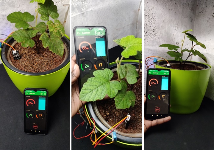
After completing the code connect nodemcu to the computer and admin/upload the code. Now turn on your wifi hotspot and open the blynk app. now we can monitor and control our plant health from anywhere in the world.
If you are confused with any steps you can refer to the making video also you can ask the doubts in the comment section. Hope you learned something.Thanks for reading...
//www.edisonsciencecorner.blogspot.com #define BLYNK_PRINT Serial char auth[] = "EqF6GGkVt_kFgBJHIX0v32TrFcc_Wxy5"; // blynk token int readD1; void setup() void loop() moisture_sensor1=map(readD1, wet, dry, 100, 0);
#include <ESP8266WiFi.h>
#include <BlynkSimpleEsp8266.h>
#include <DHT.h>
char ssid[] = "edison science corner"; //ssid
char pass[] = "eeeeeeee"; //password
int readD2;
int moisture_sensor1;
int moisture_sensor2;
int Pin_D1 = 5;
int Pin_D2 = 4;
int Pin_D4 = 2;
#define DHTPIN 0
#define DHTTYPE DHT11
const int dry = 600; // value for dry sensor
const int wet = 200; // value for wet sensor
DHT dht(DHTPIN, DHTTYPE);
BlynkTimer timer;
const int dry = 600; // value for dry sensor
const int wet = 200; // value for wet sensor
{
Serial.begin(9600);
pinMode(Pin_D1,OUTPUT);
pinMode(Pin_D2,OUTPUT);
pinMode(Pin_D4,OUTPUT);
pinMode(A0,INPUT);
dht.begin();
timer.setInterval(1000L, sendSensor);
Blynk.begin(auth, ssid, pass);
}
void sendSensor()
{
float h = dht.readHumidity();
float t = dht.readTemperature(); // or dht.readTemperature(true) for Fahrenheit
Blynk.virtualWrite(V7, t);
Blynk.virtualWrite(V8 , h);
}
{
Blynk.run();
//for first sensor
digitalWrite(Pin_D1, HIGH); //Turn D1 On
delay(100);
readD1 = analogRead(0); //Read Analog value of first sensor
digitalWrite(Pin_D1, LOW); //Turn D1 Off
delay(100);
//for second sensor
digitalWrite(Pin_D2, HIGH); //Turn D2 On
delay(100);
readD2 = analogRead(0); //Read Analog value of second sensor
digitalWrite(Pin_D2, LOW); //Turn D2 Off
delay(100);
moisture_sensor2=map(readD2, wet, dry, 100, 0);
//to the serial monitor
Serial.print("sensor 1 = ");
Serial.print(readD1);
Serial.print(" / sensor 2 = ");
Serial.println(readD2);
if (moisture_sensor2<=50)
{
digitalWrite(Pin_D4,HIGH);
delay(10);
}
if (moisture_sensor2>50)
{
digitalWrite(Pin_D4,LOW);
delay(10);
}
Blynk.virtualWrite(V5, moisture_sensor1); // to Blynk server
Blynk.virtualWrite(V6, moisture_sensor2); // to Blynk server
timer.run();
}