
Alternating Current (AC) power supply is used for almost all the residential, commercial and industrial needs. But the biggest issue with AC is that it cannot be stored for future use. So AC is converted into DC and then DC is stored in batteries and ultra-capacitors. And now whenever AC is needed, DC is again converted into AC to run the AC based appliances. So the device which converts DC into AC is called Inverter. The inverter is used to convert DC to variable AC. This variation can be in the magnitude of voltage, number of phases, frequency or phase difference.
Classification of Inverter
Inverter can be classified into many types based on output, source, type of load etc. Below is the complete classification of the inverter circuits:
(I) According to the Output Characteristic
- Square Wave Inverter
- Sine Wave Inverter
- Modified Sine Wave Inverter
(II) According to the Source of Inverter
- Current Source Inverter
- Voltage Source Inverter
(III) According to the Type of Load
- Single Phase Inverter
- Half Bridge Inverter
- Full Bridge Inverter
- Three Phase Inverter
- 180-degree mode
- 120-degree mode
(IV) According to different PWM Technique
- Simple Pulse Width Modulation (SPWM)
- Multiple Pulse Width Modulation (MPWM)
- Sinusoidal Pulse Width Modulation (SPWM)
- Modified sinusoidal Pulse Width Modulation (MSPWM)
(V) According to Number of Output Level
- Regular Two-Level Inverter
- Multi-Level Inverter
Now we will discuss all of them one by one. You can check a sample 12v DC to 220v AC Inverter Circuit design here.
(I) According to the Output Characteristic
According to the output characteristic of an inverter, there can be three different types of inverters.
- Square Wave Inverter
- Sine Wave Inverter
- Modified Sine Wave Inverter
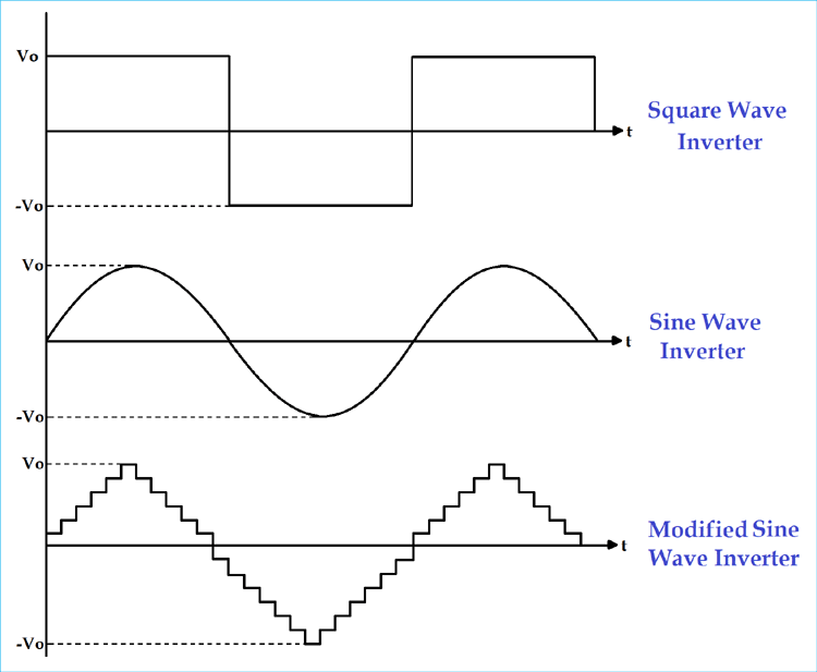
1) Square wave inverter
The output waveform of the voltage for this inverter is a square wave. This type of inverter is least used among all other types of inverter because all appliances are designed for sine wave supply. If we supply square wave to sine wave based appliance, it may get damaged or losses are very high. The cost of this inverter is very low but the application is very rare. It can be used in simple tools with a universal motor.
2) Sine wave
The output waveform of the voltage is a sine wave and it gives us a very similar output to the utility supply. This is the major advantage of this inverter because all the appliances we are using, are designed for the sine wave. So, this is the perfect output and gives guarantee that equipment will work properly. This type of inverters is more expensive but widely used in residential and commercial applications.
3) Modified sine wave
The construction of this type of inverter is complex than simple square wave inverter but easier compared to the pure sine wave inverter. The output of this inverter is neither pure sine wave nor the square wave. The output of such inverter is the some of two square waves. The output waveform is not exactly sine wave but it resembles the shape of a sine wave.
(II) According to the Source of the Inverter
- Voltage Source Inverter
- Current Source Inverter
1) Current Source Inverter
In CSI, the input is a current source. This type of inverters is used in the medium voltage industrial application, where high-quality current waveforms are compulsory. But CSIs are not popular.
2) Voltage Source Inverter
In VSI, the input is a voltage source. This type of inverter is used in all applications because it is more efficient and have higher reliability and faster dynamic response. VSI is capable of running motors without de-rating.
(III) According to the Type of Load
- Single-phase Inverter
- Three-phase Inverter
1) single-phase inverter
Generally, residential and commercial load uses single phase power. The single-phase inverter is used for this type of application. The single-phase inverter is further divided into two parts;
- Single Phase Half-bridge Inverter
- Single Phase Full-bridge Inverter
A) Single Phase Half bridge Inverter
This type of inverter consists of two thyristors and two diodes and connection is as shown in below figure.
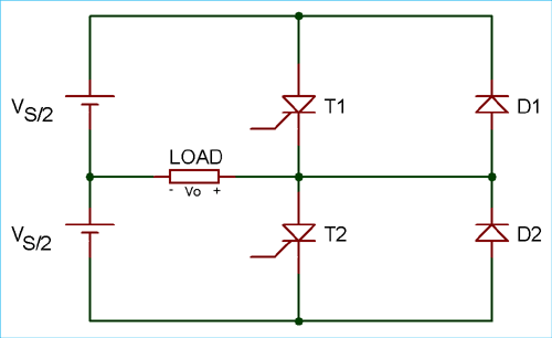
In this case, total DC voltage is Vs and divided into two equal parts Vs/2. Time for one cycle is T sec.
For half cycle of 0 <t <T/2, thyristor T1 conducts. The load voltage is Vs/2 due to the upper voltage source Vs/2.
For the second half cycle of T/2 <t <T, thyristor T1 is commutated and T2 conducts. During this period, the load voltage is -Vs/2 due to the lower source Vs/2.
Vo = Vs/2
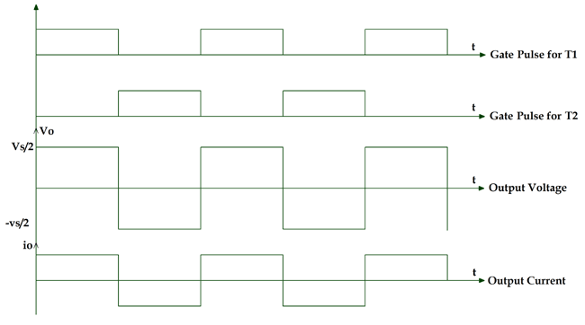
By this operation, we can get alternating voltage waveform with 1/T Hz frequency and Vs/2 peak amplitude. The output waveform is a square wave. It will be passed through the filter and remove unwanted harmonics which give us pure sine waveform. The frequency of the waveform can be controled by the ON time (Ton) and OFF time (Toff) of the thyristor.
The magnitude of the output voltage is half of the supply voltage and source utilization period is 50%. This is a disadvantage of half bridge inverter and solution of this is full bridge inverter.
B) Single Phase Full-bridge Inverter
In this type of inverter, four thyristors and four diodes are used. The circuit diagram of single-phase full bridge is as shown in below figure.
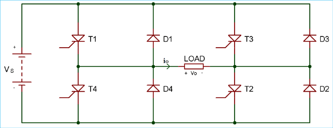
At a time two thyristors T1 and T2 conduct for first half cycle 0 < t < T/2. During this period, the load voltage is Vs which is similar to the DC supply voltage.
For second half cycle T/2 < t < T, two thyristors T3 and T4 conducts. The load voltage during this period is -Vs.
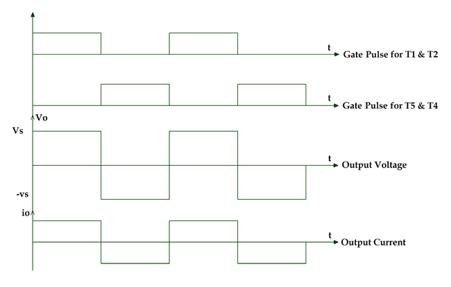
Here we can get AC output voltage same as DC supply voltage and the source utilization factor is 100%. The output voltage waveform is square waveform and the filters are used to convert it into a sine wave.
If all thyristors conduct at the same time or in a pair of (T1 and T3) or (T2 and T4) then the source will be short-circuited. The diodes are connected in the circuit as feedback diode because it is used for the energy feedback to the DC source.
If we compare full bridge inverter with half bridge inverter, for the given DC supply voltage load, output voltage is two times and output is power is four times in full bridge inverter.
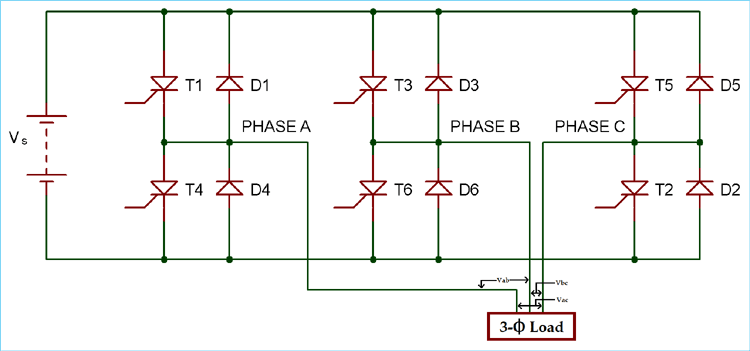
2) Three Phase Bridge Inverter
In case of industrial load, three phase ac supply is used and for this, we have to use a three-phase inverter. In this type of inverter, six thyristors and six diodes are used and they are connected as shown in below figure.
It can operate in two modes according to the degree of gate pulses.
- 180-degree mode
- 120-degree mode
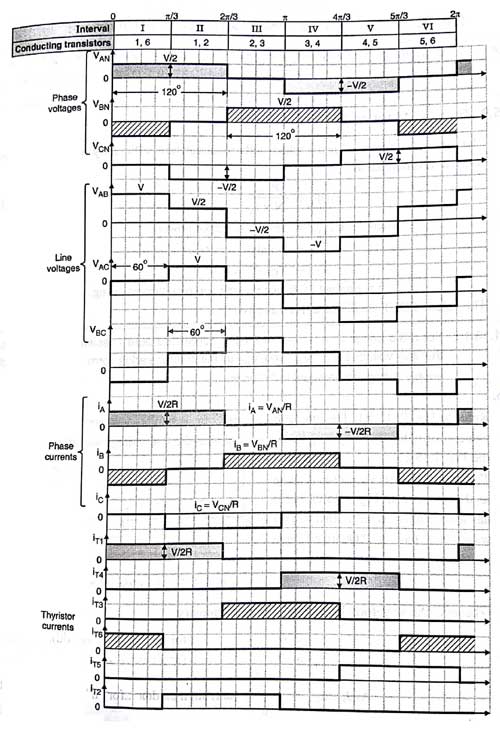
A) 180-degree mode
In this mode of operation, conduction time for thyristor is 180 degree. At any time of period, three thyristors (one thyristor from each phase) are in conduction mode. The shape of phase voltage is three stepped waveforms and shape of line voltage is a quasi-square wave as shown in the figure.
Vab = Va0 – Vb0
Vbc = Vb0 – Vc0
Vca = Vc0 – Va0
|
Phase A |
T1 |
T4 |
T1 |
T4 |
|||||||||
|
Phase B |
T6 |
T3 |
T6 |
T3 |
T6 |
||||||||
|
Phase C |
T5 |
T2 |
T5 |
T2 |
T5 |
||||||||
|
Degree |
60 |
120 |
180 |
240 |
300 |
360 |
60 |
120 |
180 |
240 |
300 |
360 |
|
|
Thyristor conducts |
1 5 6 |
6 1 2 |
1 2 3 |
2 3 4 |
3 4 5 |
4 5 6 |
1 5 6 |
6 1 2 |
1 2 3 |
2 3 4 |
3 4 5 |
4 5 6 |
|
In this operation, the time gap between the commutation of outgoing thyristor and conduction of incoming thyristor is zero. So the simultaneous conduction of incoming and outgoing thyristor is possible. It results in a short circuit of the source. To avoid this difficulty, 120-degree mode of operation is used.
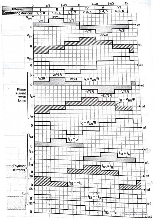
B) 120-degree mode
In this operation, at a time only two thyristors conduct. One of the phases of the thyristor is neither connected to the positive terminal nor connected to the negative terminal. The conduction time for each thyristor is 120 degree. The shape of line voltage is three stepped waveform and shape of the phase voltage is a quasi-square waveform.
|
Phase A |
T1 |
|
T4 |
|
T1 |
|
T4 |
|
||||
|
Phase B |
T6 |
|
T3 |
|
T6 |
|
T3 |
|
T6 |
|||
|
Phase C |
|
T2 |
|
T5 |
|
T2 |
|
T5 |
||||
|
degree |
60 |
120 |
180 |
240 |
300 |
360 |
60 |
120 |
180 |
240 |
300 |
360 |
|
Thyristor conducts |
1 6 |
2 1 |
3 2 |
3 4 |
4 5 |
6 5 |
1 6 |
2 1 |
3 2 |
3 4 |
4 5 |
5 6 |
The waveform of line voltage, phase voltage and gate pulse of the thyristor is as shown in the above figure.
In any power electronic switches, there are two types of losses; conduction loss and switching loss. The conduction loss means ON state loss in the switch and the switching loss means OFF state loss in switch. Generally, the conduction loss is greater than the switching loss in most of the operation.
If we consider 180-degree mode for one 60-degree operation, three switches are open and three switches are closed. Means total loss is equal to three times of conduction loss plus three times of switching loss.
Total loss in 180-degree = 3 (conductance loss) + 3 (switching loss)
If we consider 120-degree mode for one 60-degree operation, two switches are open and rest of the four switches are closed. Means total loss is equal to two times of conductance loss plus four times of switching loss.
Total loss in 120-degree = 2 (conductance loss) + 4 (switching loss)
(IV) Classification According to Control Technique
- Single Pulse Width modulation (single PWM)
- Multiple Pulse Width Modulation (MPWM)
- Sinusoidal Pulse Width Modulation (SPWM)
- Modified Sinusoidal Pulse Width Modulation (MSPWM)
The output of the inverter is square wave signal and this signal is not used for the load. Pulse width modulation (PWM) technique is used to control AC output voltage. This control is obtained by the controlling of ON and OFF period of switches. In PWM technique two signals are used; one is reference signal and second is triangular carrier signal. The gate pulse for switches is generated by comparing these two signals. There are different types of PWM techniques.
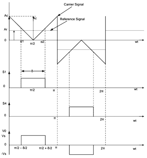
1) Single Pulse Width modulation (single PWM)
For every half cycle, the only pulse is available in this control technique. The reference signal is square wave signal and the carrier signal is triangular wave signal. The gate pulse for the switches is generated by comparing the reference signal and carrier signal. The frequency of output voltage is controlled by the frequency of the reference signal. The amplitude of the reference signal is Ar and the amplitude of the carrier signal is Ac, then the modulation index can be defined as Ar/Ac. The main drawback of this technique is high harmonic content.
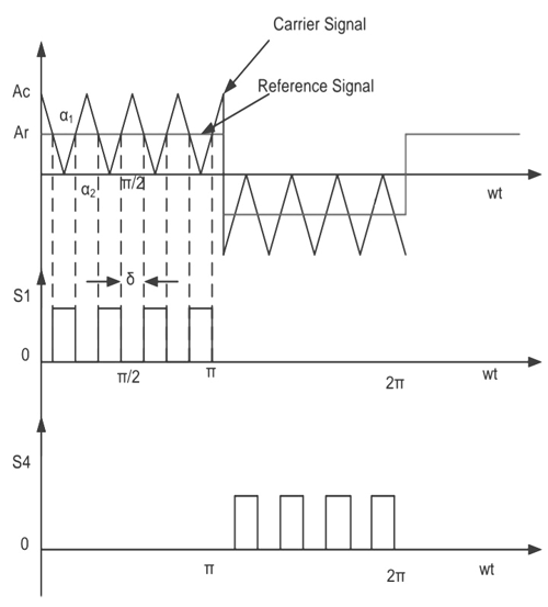
2) Multiple Pulse Width Modulation (MPWM)
The drawback of single pulse width modulation technique is solved by multiple PWM. In this technique, instead of one pulse, several pulses are used in each half cycle of the output voltage. The gate is generated by comparing the reference signal and carrier signal. The output frequency is controlled by controlling the frequency of the carrier signal. The modulation index is used to control the output voltage.
The number of pulses per half cycle = fc/ (2*f0)
Where fc = frequency of carrier signal
f0 = frequency of output signal
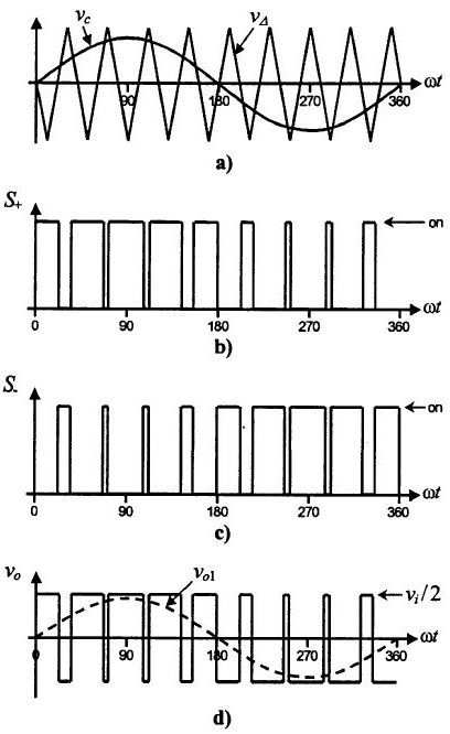
3) Sinusoidal Pulse Width Modulation (SPWM)
This control technique is widely used in industrial applications. In above both methods, the reference signal is a square wave signal. But in this method, the reference signal is a sine wave signal. The gate pulse for the switches is generated by comparing the sine wave reference signal with the triangular carrier wave. The width of each pulse varies with variation of amplitude of the sine wave. The frequency of output waveform is the same as the frequency of the reference signal. The output voltage is a sine wave and the RMS voltage can be controlled by modulation index. Waveforms are as shown in below figure.
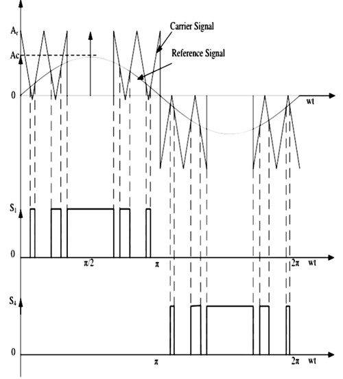
4) Modified Sinusoidal Pulse Width Modulation (MSPWM)
Due to the characteristic of sine wave, the pulse width of the wave cannot be changed with variation in the modulation index in SPWM technique. That is the reason, MSPWN technique is introduced. In this technique, the carrier signal is applied during the first and last 60-degree interval of each half cycle. In this way, its harmonic characteristic is improved. The main advantage of this technique is increased fundamental component, reduced number of switching power devices and decreased switching loss. The waveform is as shown in below figure.
(V) According to the Number of Levels at the Output
- Regular Two-Level Inverter
- Multi-level Inverter
1) Regular two-level Inverter
These inverters have only voltage levels at the output which are positive peak voltage and negative peak voltage. Sometimes, having a zero-voltage level is also known as a two-level inverter.
2) Multilevel Inverters
These inverters can have multiple voltage levels at the output. The multi-level inverter is divided into four parts.
- Flying capacitor Inverter
- Diode-clamped Inverter
- Hybrid Inverter
- Cascade H-type Inverter
Every inverter has its own design for operation, here we have explained these inverter briefly to get an basic ideas about them.
