

SPI is a crucial communication protocol that is widely used to communicate among microcontrollers, SD cards, and various other sensors. SPI stands for Serial Peripheral Interface, it's a synchronous data transfer protocol where the master device could communicate with multiple slave devices as well as get data from them. It is synchronous because the master generates a clock in a separate I/O line that guarantees that both devices, master and the slave are running at the same clock speed.
SPI protocol uses two data lines, one selection line, and one clock line. The connections are SS (Slave Select), MISO (Master In Slave Out), MOSI (Master Out Slave In), and SCK (Serial Clock). Despite an SCK line, the master generates a clock, and the SS is used for selecting any individual slave in a bus line where multiple slave devices are connected with the master. MISO is used to receive the data from the slave, and MOSI is used to send data from the master to the slave device.
Previously, we have built many projects which utilize SPI protocol, in order to communicate in between sensors, so do check those out if you want to learn a bit more about the topic. Also, if you want to start with the basics of a Nuvoton N76E003 board, do consider checking the getting started with nuvoton guide
Hardware Setup and Requirements to Enable SPI Function on N76E003
The objective of this project is to learn SPI communication using N76E003, and the best way is to set up an SPI example in which we transfer a message between two microcontroller units, to do so, we will use an Arduino as a slave device that is connected with the N76E003 SPI line. We will send data to the Arduino, validate it, and print it using Arduinos UART. Next, we send a data from Arduino to the N76E003, validate it, and print it using N76E003 UART, that is why a USB to UART converter for the N76E003 and an Arduino becomes necessary for our example application, we will use CP2102 UART to USB converter, and an Arduino Nano to fulfill our requirements.
Not to mention, other than the above things, we need the N76E003 microcontroller-based development board as well as the Nu-Link Programmer to program the board. Additionally, berg wires are used for all the hardware connections.
While back we made some articles like RS-485 MODBUS Serial Communication with Arduino as Master, and Arduino to Arduino Bluetooth Communication using Master-Slave Configuration where we have setup an Arduino as a master device, feel free to check those out if that peaks your interest.
Circuit to Interface N76E003 with Arduino via SPI
As we can see in the schematic, the Arduino Nano is connected with the SPI of N76E003. On the extreme left, the programming interface connection is shown.

SPI Pins on Nuvoton N76E003 Microcontroller
The pin diagram of N76E003 can be seen in the below image-
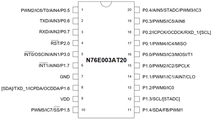
As we can see in the above pin diagram, each pin has multiplexed functional specifications, and each can be programmed depending upon the application. However, pins 0.1, 0.0, 1.0, and 1.5 are used as MISO, MOSI, SPCLK, and SS pins respectively. If we enable SPI, it'll lose PWM and other functionality. But, that is not a problem as another functionality is not required for this project. This chip considers all the SPI pins as GPIO, which is why those needs to be configured. The configuration method is described below.
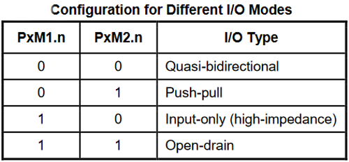
As per the datasheet, PxM1.n, and PxM2.n are two registers that are used to determine the control operation of the I/O port. In the N76E003 datasheet, it is stated that to use the SPI functionality, the I/O modes need to be used as Quasi mode for SPI communications.
SPI Information N76E003
The SPI peripheral is a must-have feature for any microcontroller, not only it's easy to use, but it can achieve the fastest transfer speeds among many other generic communication protocols, which is why different types of microcontrollers come with an in-built SPI peripheral.
Before proceeding with SPI communication, it is important to know a few things about SPI communication on N7E003.
SS Pin of the N76E003:
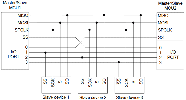
It is an important pin in SPI communication. The Slave Select pin selects specific slaves in a multi slave SPI bus. All individual slaves must require one slave select pin. A single SS pin cannot be connected to multiple slaves.
The below image is showing the possible multiple slave connections-
Selection of the MSB First or LSB First bit in N76E003:
N76E003 supports two types of data communication - MSB first or LSB first. By default, the MSB first is selected. However, LSB's first data can also be selected in N76E003. We will take care of this selection in the coding process.
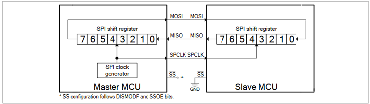
The simple SPI connection with Single-Master and Single-Salve is shown in the below image-
SPI Peripheral Control Register (SPCR) of the N76E003:
SPI control register SPCR is used to control the SPI operations.
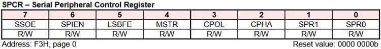
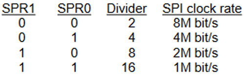
The first two bits are the SPI clock rate selection bit. The clock rates are illustrated below where the system frequency is 16 Mhz.
CPHA bit is the clock phase select bit. If the CPHA flag is set, the data is sampled on the second edge of the SPI clock. If it is cleared, then the data is sampled on the first edge. The next bit is CPOLI which is the idle state level of the SPI clock. If set to 0, the clock will be low in idle state, if it is set to 1, it will be high in idle state. The MSTR is the Master mode enable bit, which is used to configure the N76E003 as a master mode, clearing this bit will make it a slave mode. LSBFE is used to data transfer direction. Clearing this bit will make the data transfer as MSB first, whereas setting it 1 will activate the LSB first direction. SPIEN is used to enable the SPI. Setting 1 will enable the SPI peripheral. The final SSOE is the SPI slave select output enable bit, and it is used for configuring the SS pin as general-purpose or in automatic mode.
Other than the above, there is another register called the Serial Peripheral Status register.
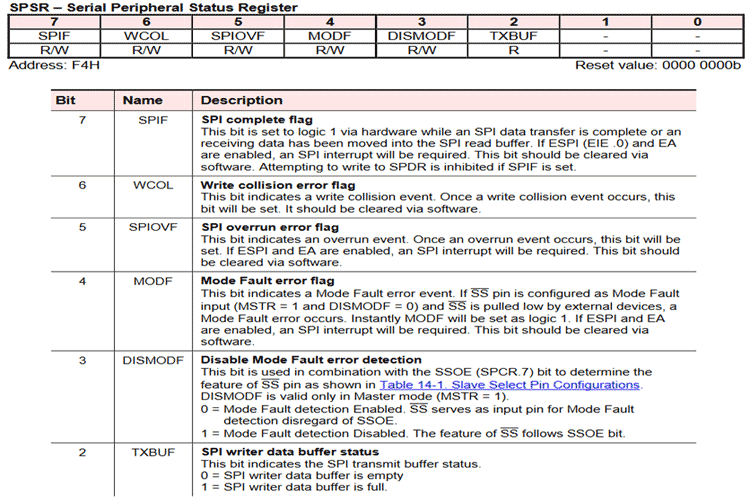
The above register is used to get the various SPI status.
Master N76E003 SPI Programming Explanation
The main function is simple, it will initiate the SPI peripheral and the UART, also it will call the Start_Sending_SPI(); function in the while loop. If you are new with using UART with Nuvoton, check out the linked tutorial.
void main(void)
{
                Set_All_GPIO_Quasi_Mode;
                InitialUART0_Timer1(115200); /* 115200 Baud Rate*/
                SPI_Initial();
                printf ("\nSPI Start Transmit...\n");
                while(1)  // SPI transmission finish
                {
                Start_Sending_SPI();
                }
}
Let’s take a look at the SPI_Initial(); function.
void SPI_Initial(void)
{
                 P15_Quasi_Mode;    // P15 (SS) Quasi mode
                 P10_Quasi_Mode;   // P10(SPCLK) Quasi mode
                 P00_Quasi_Mode;  // P00 (MOSI) Quasi mode
                P01_Quasi_Mode;  // P22 (MISO) Quasi mode
                set_DISMODF;    // SS General purpose I/O ( No Mode Fault )
                clr_SSOE;
                clr_LSBFE;   // MSB first
                clr_CPOL;   // The SPI clock is low in idle mode
                set_CPHA;  // The data is
sample on the second edge of SPI clock.
                set_MSTR;  // SPI in
Master mode
                SPICLK_DIV2;   // Select SPI clock
                Enable_SPI_Interrupt;   // Enable SPI interrupt
                set_SPIEN;   // Enable SPI function
}
As described before, the SPI port pins need to be configured and set as the Quasi configuration, the first four-line inside the SPI_Initial() function does exactly that, the configuration for the SPI is selected as the general-purpose SS pin, the data will be transferred as MSB first, SPI clock is low in idle mode with second edge data sampling. As N76E003 will act as Master mode, it is set as master. The SPI interrupt is set with SPI enabled bit SPIEN. These all functions are available in the SFR_Macro.h header file.
In the Start_Sending_SPI() function, the SS pin is pulled low first, the data is submitted to the Arduino via SPI. The SPDR register will hold the value to be sent to the SPI slave as well as will receive the value from the Slave.
void Start_Sending_SPI()
{
                SS = 0;
                SPDR = 0x90;    // Send 0x90 to Slave
                PCON |= SET_BIT0;   // Enter idle mode
                if(SPDR != 0x4E)   // Receive slave 1st DATA
                SPI_Error();
                printf ("\nSlave Return %x\n",SPDR & 0xFF);
                SS = 1;
}
However, there is a validation condition, where the SPRD value is checked with (0x4E) that is received from the Arduino. If the data is not 0x4E, it will stop the SPI communication by going into the while loop.
void SPI_Error(void)
{
                printf ("\nSlave stoped the Data sending.\n");
                while(1)  // SPI error and P0.7 flash/
                {
                }
    }
As the SPI used in timer interrupt, one ISR function is used here-
void SPI_ISR(void) interrupt 9    // Vecotr @  0x4B
{
            clr_SPIF;
            Timer3_Delay10us(1);
}
It will clear the SPIF with a 1-microsecond time gap.
Programming Arduino as a slave for SPI
Arduino Nano also has the same SPI pins shown in the image below-
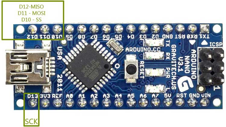
However, we will not go into the details about Arduino SPI, as there are a ton of details available showing how to use SPI on an Arduino.
First, we include all the necessary header and variables,
#include<SPI.h>
volatile boolean received;
volatile byte Slavereceived,Slavesend;
Next, in the setup section, we initialize UART, we set our predefined MISO pin as an output, we enable SPI in slave mode, we set our predefined received variable as false, and finally, we enable our interrupt, which marks the end of the setup loop.
void setup ()
{
  Serial.begin(115200);
  pinMode(MISO,OUTPUT);    //Sets MISO as OUTPUT (Have to Send data to Master IN
  SPCR |= _BV(SPE);    //Turn on SPI in Slave Mode
  received = false;
  SPI.attachInterrupt();   //Interuupt ON is set for SPI commnucation
}
Next, we have defined our interrupt service routine, in the interrupt service routine, we dump the data from SPDR Register to our predefined variable Slavereceived, we print the data using the built-in Serial.print functions and we set the received variable to true.
In the loop section, we are sending a predefined value to the SPDR register, once every second which transmits the data to the master module.
Testing SPI Communication on Nuvoton using Arduino
The complete code is given at the end of this page. The code when uploaded returned 0 warning and 0 Errors and flashed using the default flashing method by the Keil. The application starts working.
Build target 'SPI_INT_M'
linking...
Program Size: data=58.2 xdata=0 code=2402
creating hex file from ".\Output\Master_P"...
".\Output\Master_P" - 0 Error(s), 0 Warning(s).
Build Time Elapsed:  00:00:01
Batch-Build summary: 1 succeeded, 0 failed, 0 skipped - Time Elapsed: 00:00:01
I have used jumper wires to connect my nuvoton board with Arduino, my testing set-up connection is shown below.
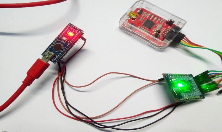
The Output of the UART can be seen in the below images. When we open the serial monitor of Arduino, we can see the values from the nuvoton board being received through SPI communication.
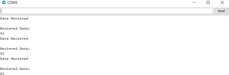
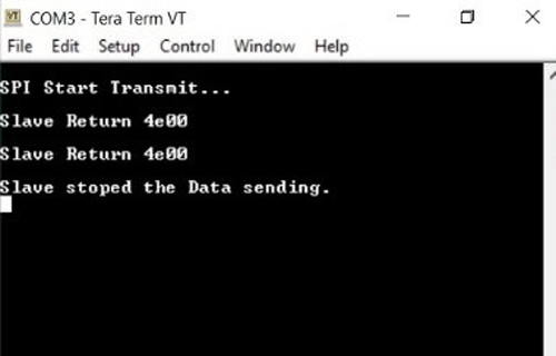
Similarly, on the nuvoton side, we have used tera term to monitor the data is being received from the slave (here Arduino). Basically, we are sending 90 from nuvoton to Arduino and sending 4e00 from Arduino to nuvoton. From the snapshots on the serial monitor, it is clear that both SPI master and slave is working as expected.
You can check out the video linked below for the complete demonstration of this tutorial. Hope you enjoyed the article and learned something useful. If you have any questions, you can leave them in the comment section below or use our forums to post other technical questions.
#Master N76E003 SPI
/*---------------------------------------------------------------------------------------------------------*/
/*                                                                                                          */
/* Copyright(c) 2017 Nuvoton Technology Corp. All rights reserved.                                                */
/*                                                                                                          */
/*---------------------------------------------------------------------------------------------------------*/
//***********************************************************************************************************
//  Website: http://www.nuvoton.com
//  E-Mail : MicroC-8bit@nuvoton.com
//  Date   : Jan/21/2017
//***********************************************************************************************************
//***********************************************************************************************************
//  File Function: N76E003 SPI in Master mode demo code
//***********************************************************************************************************
#include "N76E003.h"
#include "SFR_Macro.h"
#include "Function_define.h"
#include "Common.h"
#include "Delay.h"
//***********************************************************************************************************
//  Application: SPI Function
//  Master send 0x90 and recevie 0x4E
//  Master send 0x01 and recevie 0x55
//  Master send 0x02 and recevie 0x56
//  Master send 0x03 and recevie 0x4F
//  Master send 0x04 and recevie 0x54
//
//  Master receive 0x4E and 0x4F form slave after transmitting
//
//  Output : P1.4 & P2.1 flash when SPI pass
//          UART show result on hyper-terminal
//          P0.7 flash when SPI error
//***********************************************************************************************************
#if 0
///*****************************************************************************************
//* For ADC INIT setting
//*****************************************************************************************/
//#define             SPICLK_DIV2                           clr_SPR0;clr_SPR1
//#define             SPICLK_DIV4                           set_SPR0;clr_SPR1
//#define             SPICLK_DIV8                           clr_SPR0;set_SPR1
//#define             SPICLK_DIV16              set_SPR0;set_SPR1
//#define             Enable_SPI_Interrupt    set_ESPI;set_EA
//#define             SS        P15
#endif
//-----------------------------------------------------------------------------------------------------------
void SPI_Error(void)
{
            printf ("\nSlave stoped the Data sending.\n");
            while(1)                                     // SPI error and P0.7 flash/
            {
            }
    }
//-----------------------------------------------------------------------------------------------------------
void SPI_Initial(void)
{
             P15_Quasi_Mode;       // P15 (SS) Quasi mode
             P10_Quasi_Mode;       // P10(SPCLK) Quasi mode
             P00_Quasi_Mode;       // P00 (MOSI) Quasi mode
            P01_Quasi_Mode;        // P22 (MISO) Quasi mode
            set_DISMODF;            // SS General purpose I/O ( No Mode Fault )
            clr_SSOE;
            clr_LSBFE;                 // MSB first
            clr_CPOL;                  // The SPI clock is low in idle mode
            set_CPHA;                 // The data is sample on the second edge of SPI clock
            set_MSTR;                 // SPI in Master mode
            SPICLK_DIV2;         // Select SPI clock
            Enable_SPI_Interrupt;          // Enable SPI interrupt
            set_SPIEN;                           // Enable SPI function
}
//-----------------------------------------------------------------------------------------------------------
void Start_Sending_SPI()
{
            SS = 0;
            SPDR = 0x90;               // Send 0x90 to Slave
            PCON |= SET_BIT0;    // Enter idle mode
            if(SPDR != 0x4E)         // Receive slave 1st DATA
            SPI_Error();
            printf ("\nSlave Return %x\n",SPDR & 0xFF);
            SS = 1;
}
//-----------------------------------------------------------------------------------------------------------
void main(void)
{
            Set_All_GPIO_Quasi_Mode;
            InitialUART0_Timer1(115200);                 /* 115200 Baud Rate*/
            SPI_Initial();
            printf ("\nSPI Start Transmit...\n");
            while(1)                                     // SPI transmission finish
            {
                         Start_Sending_SPI();
            }
}
//-----------------------------------------------------------------------------------------------------------
void SPI_ISR(void) interrupt 9                 // Vecotr @  0x4B
{
            clr_SPIF;
            Timer3_Delay10us(1);
}
//-----------------------------------------------------------------------------------------------------------

#Slave Arduino SPI
#include<SPI.h>
volatile boolean received;
volatile byte Slavereceived,Slavesend;
void setup ()
{
  Serial.begin(115200);
  pinMode(MISO,OUTPUT);             //Sets MISO as OUTPUT (Have to Send data to Master IN
  SPCR |= _BV(SPE);                        //Turn on SPI in Slave Mode
  received = false;
  SPI.attachInterrupt();                        //Interuupt ON is set for SPI commnucation
}
ISR (SPI_STC_vect)                          //Inerrrput routine function
{
  Slavereceived = SPDR;       // Value received from master if store in variable slavereceived
  Serial.println("Data Recieved\n");
  Serial.println("Recieved Data: ");
  Serial.println(Slavereceived,HEX);
  received = true;                    //Sets received as True
}
void loop(){
  SPDR = 0x4E;                    //Sends the value to master via SPDR
  delay(1000);
}