
In one of our previous tutorials, we have shown you how you can interface LM35 Temperature Sensor with Arduino because it's cheap, easy to use, and requires minuscule power for stable operation. But one of the major disadvantages of the LM35 sensor is that it is analog in nature, so it's sensitive to external noise. There are a variety of sensors that may be used to solve this problem but in today's article, we thought to cover the DS18b20 temperature sensor. Not only is this sensor inexpensive and simple to use, but it also has a one-of-a-kind 1-wire communication protocol that is simple to build and supports a wide range of devices that can connect with the CPU.
DS18b20 Temperature Sensor Pinout
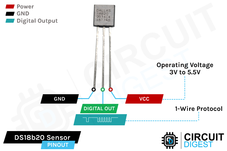
The DS18b20 Temperature Sensor IC has 3 pins VCC, GND, and Digital Out. This sensor only gives digital output. The Pinout of DS18b20 Temperature Sensor is as follows:
VCC is the supply pin of the DS18b20 Temperature Sensor that can be connected to 3.3V or 5V of the supply.
GND is the ground pin of the DS18b20 Temperature Sensor IC and it should be connected to the ground pin of the Arduino.
DOUT is the Digital Output pin of the IC that uses the 1-Wire Protocol to give out the temperature data.
DS18b20 Temperature Sensor: In-Depth
The DS18B20 is a digital thermometer that can provide 9-bit to 12-bit resolution and can measure temperatures from -55°C to +125°C. This is a unique chip designed and developed by maxim that features a proprietary 1-wire interface, this means not only it can be powered with its standard VCC and Ground pins but the DS18B20 can derive power directly from the data line. Maxim calls this feature parasitic power and we will talk about this later in the article. Other than that, this device also features a unique 64–bit ID and user-definable nonvolatile (NV) alarm settings. Each 1-wire Device from maxim comes with a unique ID which means you can put more than one device in the same bus and can access them all with a single instruction.
Now that we know the basic features of DS18b20 Temperature sensor, we can now go ahead and understand the timing diagram of the sensor. The timing diagram of the sensor is pretty simple and complicated at the same time. If you check the DS18b20 sensor Datasheet, there is no clear explanation of the communication process, so in this section, we want to clarify just that.
But before that let's see how a one-wire device is connected to the one-wire bus.
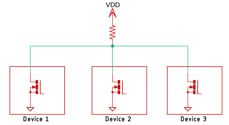
As you can see from the above image, every one-wire device comes in an open drain configuration which means every one-wire device on the 1-wire bus can pull the voltage to the ground, but no device can drive the bus high and that is why every 1-wire bus includes a pull-up resistor, the resistor value need to be adjusted according to the number of devices that are connected to the bus. A 1-wire device transmits, receives, and provides power to the devices with the same bus so it becomes important to set the resistor value according to the number of devices that are connected to the bus. The resistor value can vary from a couple of hundred ohms to kilohms. You can refer to the datasheet of the DS18b20 Temperature Sensor for more information.
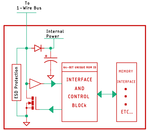
As a 1 wire bus is open-drain there is a mosfet in the IO line to pull the bus down when it's time to send data and there is also a buffer B1 to square up the signal in the IO line. For power, a diode and a capacitor are used. This is the so-called parasite power and with the help of this feature, multiple 1-wire devices can operate simultaneously when the IO line is low(the IO line gets low when data transmission occurs in the bus). Now let's assume that a stream of data is coming from the host device, in our case it's an Arduino. Now the bits that are coming from the host are presented to an interface and control circuitry that is present in every one wire device connected to the bus and it acts as a bridge between the 1-wire protocol itself and the practical device. In this interface and control unit lives the 64-bit unique identifier through which we can address any device in the one-wire bus. Now let's check out how we can send 0s and 1s in the 1-wire bus.
Transferring data through 1-wire -bus:
Transferring data to the 1-wire bus is simple and every bit is initiated by the host, whether sent from the host to one wire device or received from the one wire device. 1-wire supports 2 standard transfer speeds, one is 15.4KB/S and another one is 125KB/S.
In 1-wire timing sequence, every bit is 65us long, to send bit 1 through the 1-wire bus, the host needs to pull down the IO line and it holds it low for 1-15us, and releases the data line for the rest of the 65us bit period. To send bit 0 to the 1-wire line, the host or microcontroller needs to hold down the bus for 60-120us, and then it needs to release it for 5us at the list. This 5us bit period is super important because the first thing is it differentiates between two bits but most importantly it charges the internal parasite power capacitor to charge between bits. Now when the IO line goes high to low, it triggers a timer, and after a few microseconds later the 1-wire device samples the line. That is denoted by bit-1 and bit-0 in the above GIF image.
To initialize a transaction between the host and the device the host holds the IO line down for 480-640 uS. This long pulse is called a reset pulse and this is how a host gets the attention of all the devices on the 1-wire line. When any device on the bus recognizes a reset pulse, the device responds by holding the IO line low for 60 to 240us. This pulse is called the presence detect pulse and when the host recognizes the presence detect a pulse, the host knows at list 1 device on the bus is online and ready to send data. Once this process is complete, you can push many different types of commands in the one wire bus. The most common ones are: SKIP ROM(0xCC), READ ROM(0x33), MATCH ROM(0x55), SEARCH ROM(0xF0), and READ SCRATCHPAD(0xBE) command. You can find more information about ROM Level Commands in the 1-wire Documentation.
How does the DH18b20 Temperature Sensor Works
The gif below shows how you can read the data from the DS18b20 Temperature Sensor, as you can see to start the communication process you need to first send a reset command followed by a read scratchpad (0xBE) Command.

The scratchpad is a memory inside the DS18b20 Temperature Sensor that holds different information including the temperature data. You only need to read the first two bytes to get the temperature data out of the sensor. You can also refer to the datasheet for more information.
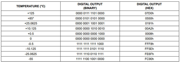
These first two bytes consist of 16 bits from which the first four bits are the sign bits. If the first four bits are zero, then it means the temperature is positive, and if the first four bits are one then that means the value is negative. The rest of the 12-bit gives out temperature data and the gif image above shows exactly how you can read that temperature data.
Commonly Asked Questions about DS18b20 Temperature Sensor IC
How accurate is DS18B20?
The DS18B20 has an accuracy of ±0.5°C from -10°C to +85°C, but it's still possible yours might be outside the error range depending on where you got them from.
Can you put DS18b20 in water?
A DS18b20 is loaded with special grade plastic to protect the circuit from corrosion, but you can find a special version of a DS18b20 sensor that is specifically designed for harsh environments. It comes in a metal enclosure sealed in resin.
Can you Connect a DS18b20 Sensor with Raspberry Pi?
Yes, it is possible to interface a DS18b20 sensor with Raspberry Pi. You just need to download the appropriate library and connect the sensor to the PI according to the circuit diagram and code.
What is the recommended pull-up resistor value for the DS18B20 sensor?
The datasheet of the DS18B20 sensor recommends a 4.7K ohms resistor as pullup but you can pull the sensor up with a 10K resistor. That should also work if you have a 10K in hand.
Interfacing DS18b20 Temperature Sensor with Arduino UNO
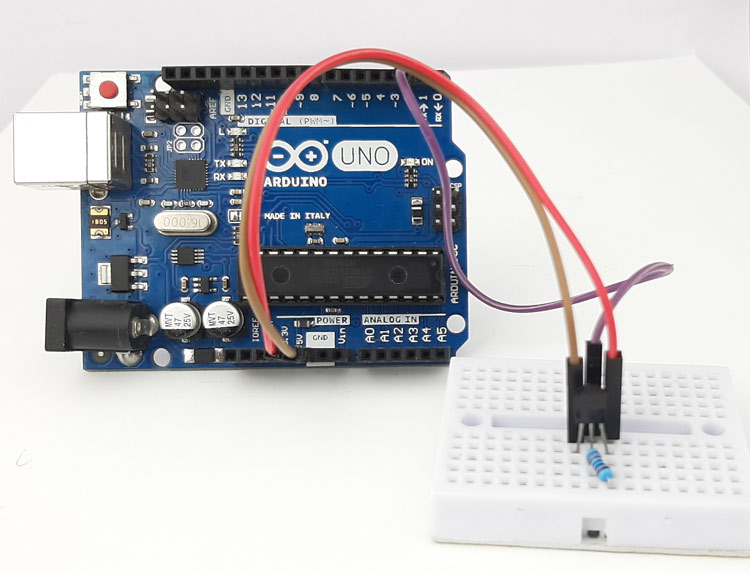
Now that we have understood how the DS18b20 Temperature Sensor works we can connect all the required wires to Arduino UNO. The Connection Diagram to Interface DS18b20 Temperature Sensor is shown below-

As you can see in the above image, connecting the DS18b20 Temperature Sensor to Arduino is very simple and easy to understand, You just need to connect 5V power to the sensor and you need to connect the output of the sensor to the D2 pin of the Arduino. Once the connection is done, you need to write the code to convert the digital output data to temperature data and for that, you can download the library from the library manager of the Arduino.
Arduino Code for Interfacing DS18b20 Temperature Sensor Module
The code to acquire data from DS18b20 Sensor is very simple and easy to understand. We just need to include the required libraries for the Arduino and we can load up the example sketch for that. If everything is connected correctly, we can see the output data on the serial monitor window, but let's just not take the easy way and try to understand how the code works.
We initialize our code by including all the required libraries and we define the pin to which the DS18b20 temperature sensor is connected.
// Include the libraries we need
#include <OneWire.h>
#include <DallasTemperature.h>
// Data wire is plugged into port 2 on the Arduino
#define ONE_WIRE_BUS 2
Next, we make two instances, one handles the one wire protocol and the other one handles the DS18b20 sensor. We pass the one wire instance through the Dallas Temperature instance.
// Setup a oneWire instance to communicate with any OneWire devices (not just Maxim/Dallas temperature ICs)
OneWire oneWire(ONE_WIRE_BUS);
// Pass our oneWire reference to Dallas Temperature.
DallasTemperature sensors(&oneWire);
Next, we have our setup() function, in the setup function we enable the serial with the begin method and we print a statement so that we can be sure that the serial monitor is working properly.
void setup(void)
{
  // start serial port
  Serial.begin(9600);
  Serial.println("Dallas Temperature IC Control Library Demo");
  // Start up the library
  sensors.begin();
}
Next, we have our loop function, in the loop function, we first request data from the sensor with the help of the sensors.requestTemperatures() command. We also print statements on the serial monitor window to check if the process was completed successfully or not.
// call sensors.requestTemperatures() to issue a global temperature
  // request to all devices on the bus
  Serial.print("Requesting temperatures...");
  sensors.requestTemperatures(); // Send the command to get temperatures
  Serial.println("DONE");
Next, we store the received read data from the local variable named tempC and in the next line, we check if it was successful or not. If the data acquisition was successful, we print the temperature on the serial monitor window else we print an error message on the serial monitor window.
// We use the function ByIndex, and as an example get the temperature from the first sensor only.
  float tempC = sensors.getTempCByIndex(0);
  // Check if reading was successful
  if(tempC != DEVICE_DISCONNECTED_C)
  {
    Serial.print("Temperature for the device 1 (index 0) is: ");
    Serial.println(tempC);
  }
  else
  {
    Serial.println("Error: Could not read temperature data");
  }
}
This marks the end of the code part in our artificial.
Practical Implementation of DS18b20 Temperature Sensor
The gif below shows the Arduino with the DS18b20 Temperature Sensor in action. On the left-hand side, we have placed the Arduino with the temperature sensor connected to the D2 pin of the Arduino and on the right-hand side, we have our serial monitor window. When we warm up the temperature sensor with the hot air station, you can see the temperature rise on the serial monitor window.
Error in DS18B20 Temperature Sensor Reading- Hear is what you should do
- Check -ve and +ve leads are connected correctly.
- Check the Operating voltage of the Device (3.0V to 5V is the normal operating voltage)
- If you have more than one DS18b20 Temperature Sensors check the value of the pullup resistor.
- If you are interfacing the DS18b20 Temperature Sensor with Arduino check out if you are using the correct library.
Projects using Arduino DS18B20 Temperature Sensor Module

If you are looking for an interesting project on the internet this project could be for you. Because in this project we have used the popular DS18b20 sensor and plethora of other sensors to build a NodeMCU based smart agriculture monitoring system that can be helpful for farmers.

Solar system and solar power is growing rapidly every passing day. That is why in this project we have tried to build a DS18b20 based IoT enabled Lithium battery monitoring system which uses a DS18b20 temperature sensor to measure the temperature of the Battery packs and send the data to the cloud.

If you are trying to build a mesh network with ESP8266, ESP32, and Arduino, this is the project that you're looking for. Not only we build a mesh network with the ESPs, but we also interface DS18b20, DHT22, and BME280 temperature sensors with those.

If you are trying to interface a DS18b20 Sensor with Raspberry Pi then this is the project you are looking for, because in this project we have shown you how to do just that in a step-by-step manner.
Supporting Files


// Include the libraries we need
#include <OneWire.h>
#include <DallasTemperature.h>
// Data wire is plugged into port 2 on the Arduino
#define ONE_WIRE_BUS 2
// Setup a oneWire instance to communicate with any OneWire devices (not just Maxim/Dallas temperature ICs)
OneWire oneWire(ONE_WIRE_BUS);
// Pass our oneWire reference to Dallas Temperature.
DallasTemperature sensors(&oneWire);
/*
* The setup function. We only start the sensors here
*/
void setup(void)
{
// start serial port
Serial.begin(9600);
Serial.println("Dallas Temperature IC Control Library Demo");
// Start up the library
sensors.begin();
}
/*
* Main function, get and show the temperature
*/
void loop(void)
{
// call sensors.requestTemperatures() to issue a global temperature
// request to all devices on the bus
Serial.print("Requesting temperatures...");
sensors.requestTemperatures(); // Send the command to get temperatures
Serial.println("DONE");
// After we got the temperatures, we can print them here.
// We use the function ByIndex, and as an example get the temperature from the first sensor only.
float tempC = sensors.getTempCByIndex(0);
// Check if reading was successful
if(tempC != DEVICE_DISCONNECTED_C)
{
Serial.print("Temperature for the device 1 (index 0) is: ");
Serial.println(tempC);
}
else
{
Serial.println("Error: Could not read temperature data");
}
}
