

Drones have rapidly evolved from niche hobbies to versatile tools with a wide range of applications, from photography to agriculture or even for defence and military purposes. Building a DIY ESP32 drone project is an affordable entry point into drone technology, with costs ranging from pocket change to commercial-grade systems. Even though the basic principle behind these drones may appear simple, there is a lot of technology and computation that goes behind it for proper operations. For example, an ESP32 drone flight controller maintains stability while in the air using precision sensors such as a Gyroscope and proper processing algorithms. In this project, we are going to build a complete ESP32 drone code that can be easily controlled using our smartphones. If you are an ESP32 fan, you can also check out our other ESP32 projects, which we built earlier.
DIY ESP32 Drone Flight Controller - Quick Overview
Build Time: 6-8 hours | Cost: $30-50 | Difficulty: Intermediate
What You'll Learn: ESP32 firmware flashing, MPU6050 IMU integration, PWM motor control, WiFi smartphone connectivity
Applications: Indoor flying practice, Educational drone prototyping, Sensor upgrades for position hold, Basic aerial photography
Update: This ESP32 drone project has now evolved and is called LiteWing - ESP32-based programmable Drone. We have improved the design and functionality, you can now program and control the drone not just from the ESP-Drone mobile application, but also cfclient and cflib Python API. The complete ESP32 drone GitHub repository now includes advanced features like height hold, position hold. This means you can program your ESP32 drone using Python and implement more features like height hold, position hold, gesture control, etc.
This DIY drone is small in size and can be built using easily available components such as ESP32 modules, MPU6050 IMU, coreless motors, and plastic propellers. Check out our collection of drone projects designed for makers and hobbyists.
Table of Contents
- Key Features
- ESP32 Drone vs Commercial Drone
- Components Required
- Circuit Diagram
- PCB Design and Layout
- Motor Rotation & Propeller Direction Configuration
- Three Methods to Flash ESP32 Drone Firmware
- └ ⇒ Method 1: Building from Source using ESPIDF
- └ ⇒ Method 2: Using ESPTOOL
- └ ⇒ Method 3: Using ESP32 Flash Download Tool
- Using The Drone
- Preflight Check
- GitHub Repository
Key Features of This ESP32 Drone Flight Controller
This ESP32 drone project incorporates professional-grade features typically found in commercial flight controllers, making it an excellent learning platform and functional quadcopter for indoor flying.
» WiFi controlled: The Drone using ESP32 can be controlled using a smartphone.
» MPU6050 IMU for stability control.
» All-in-one PCB: Doesn’t need any 3D printed parts or such.
» Easily upgradable: Additional features such as position hold or height hold can be added using external modules.
» Small size and lightweight.
» Built-in battery charger.
» Built-in USB interface for programming and debugging. » Android and IOS apps.
» Open source
ESP32 Drone vs Commercial Drone Controller Comparison
| Feature | ESP32 Drone Controller | Commercial Controller |
| Control Method | WiFi (Smartphone App) | RF Remote 2.4GHz |
| Stabilization | MPU6050 6-axis IMU | 9-axis IMU + Barometer |
| Programmability | Fully Open Source (C/Python) | Limited/Closed |
| Build Cost | $30-$50 | $100-$300 |
| Expandability | Modular (GPS, Camera, Sensors) | Fixed Configuration |
| Learning Value | Excellent (Full Access) | Limited |
Components Required to Build the ESP32 Drone Flight Controller
The components required to build the DIY WiFi-controlled drone are listed below. The exact value of each component can be found in the schematics or the BOM. Building this ESP32 drone project requires specific electronic components, each playing a critical role in flight control, power management, and wireless communication.
- ESP32 Wroom Module – x1
- CP2102N USB - UART controller – x1
- MPU6050 IMU – x1
- TP4056 Li-ion charger IC – x1
- MIC5219-3.3YM5 3.3v LDO – x1
- AO3401 P - MOSFET – x1
- 2N7002DW dual N-MOSFET – x1
- SI2302 N - MOSFET – x4
- SS34 Diode – x1
- 1N4148 Diode – x4
- SD Card Reader – x1
- Type C USB Connector 16Pin – x1
- LiPo Battery 1300mAh 30C – x1
- 720 Coreless Motor – x4
- 55mm propeller type A(CW) – x2
- 55mm propeller type B(CCW) – x2
- 7mm rubber grommet – x4
- SMD resistors and capacitors
- SMD LEDs
- SDM Slide Switch
- Connectors
- Custom PCB
- 3D printed Enclosure and mounting screws
- Other tools and consumables.
Complete ESP32 Drone Build Cost Breakdown
Here is the approximate cost of building the drone. Please note that the costs provided here are approximate and may vary depending on the vendor. The prices are calculated based on the cheapest options available from reputed vendors, with only the bare minimum number of components as the minimum MOQ. One of the major advantages of this ESP32 drone project is its affordability.
| Capacitor, Resistors, diodes & MISC | ₹ 100.00 |
| MOSFETS | ₹ 40.00 |
| ESP32 | ₹ 240.00 |
| TP4056 | ₹ 17.50 |
| MPU6050 | ₹ 140.00 |
| CP2102 | ₹ 200.00 |
| 720 Motors + 55mm propellers | ₹ 266.00 |
| PCB | ₹ 100.00 |
| Total | ₹ 1093.50 |
ESP32 Drone Circuit Diagram - Complete Schematics
The complete ESP32 drone circuit diagram for the DIY WiFi Controlled Drone is shown below. It can also be downloaded in PDF format from the link given at the end. The circuit design for this ESP32 drone flight controller integrates multiple subsystems, including power management, motor control, sensor interface, and wireless communication.

Let’s discuss the Schematics section by section for better understanding. A type C USB port is used for both charging as well as programming purposes. The power from the USB port is connected to a power path controller circuit built around a P-Channel MOSFET U2 and a diode D1. When the USB power is available, the device will operate from the USB power and will also charge the internal battery. When the USB power is cut, the device will automatically change to battery power. For voltage regulation, we have used a MIC5219 3.3V LDO from Microchip, which is capable of providing up to 500mA of current with a very low dropout voltage of 500mV at full load. A slide switch with a pull-up resistor is connected to the enable pin of MIC5219. This switch is used for turning on and off the thermal camera. When this pin is pulled to the ground, the LDO will be shut down, and hence the other parts of the device too, except the battery charging section. For charging the internal battery, we are using a TP4056 charge controller, which is capable of a maximum charge current of 1A. For battery voltage sensing, we have used a classic voltage divider, which will reduce the battery voltage to a safe level for measurement.

In the next section, we have the ESP32 SoC itself, along with the programming circuit and the MPU6050 PMU chip. The programming circuit consists of a CP2102 USB to UART controller along with a 2N7002DW dual N – N-N-Channel MOSFET from ON Semi. We have used the CP2102 with the QFN28 package. The tiny dual MOSFET will act as an auto-reset circuit for the ESP32, thus removing any need for manual reset or boot selection circuitry, reducing board size and BOM cost. The circuit around the ESP32 is standard, just bypass capacitors and pull-up resistors. The MPU6050 PMU is used for flight stabilisation and motion control. It is interfaced with the ESP32 SoC using the standard I2C pins GPIO21 and GPIO22.
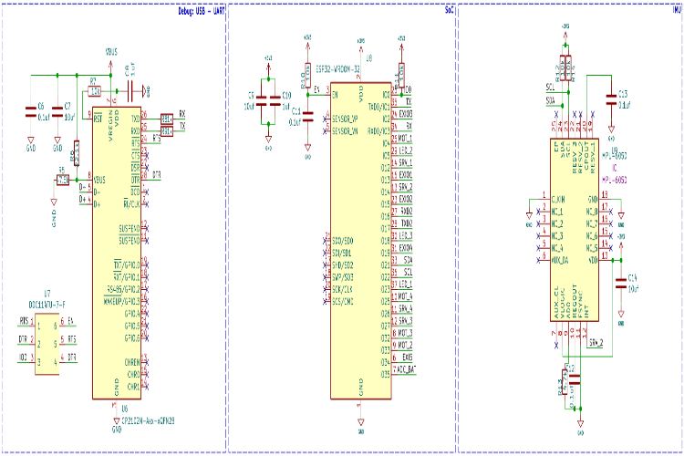
In the last section, we had the motor driver circuit. Each motor driver circuit consists of an SI2302 N-Channel MOSFET along with a flyback diode and pulldown resistor. There are 4 such circuits, for each motor. When a high signal is applied to the gate of the driver MOSFET, it will turn on and drive the motor. We will be using PWM signals to control the motor speed. The flyback diode and the capacitors are in place to protect the circuit from any back EMF or voltage spikes.
We have also added three LEDs for debugging purposes, apart from the power and charging indicators. The blue LED will blink slowly during sensor calibration and will blink at a fast pace, indicating the system is ready for takeoff. The green LED will start blinking when a UDP connection is detected from the controller app. The RED LED is used to indicate low battery status; it will light full-time if the battery voltage is low.

ESP32 Drone PCB Design and Layout Considerations
The custom PCB for this ESP32 drone project serves as both the flight controller and structural frame. For this project, we have decided to make a custom PCB. This ESP32 drone PCB design ensures that the final drone is as compact as possible while remaining easy to assemble and use. We have also designed the PCB in a way that the feet for the drone are also included in the PCB and can be easily broken away from the main PCB. Here are the top and bottom layers of the PCB.

Here is the PCB.


Here is the 3D render of the fully assembled drone.
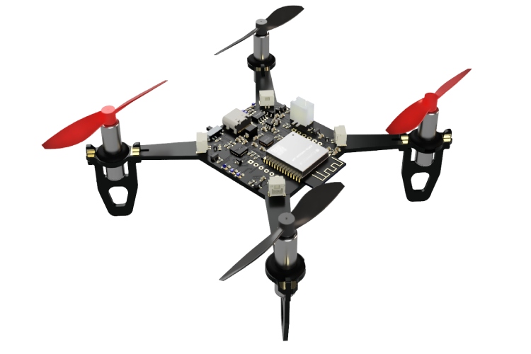
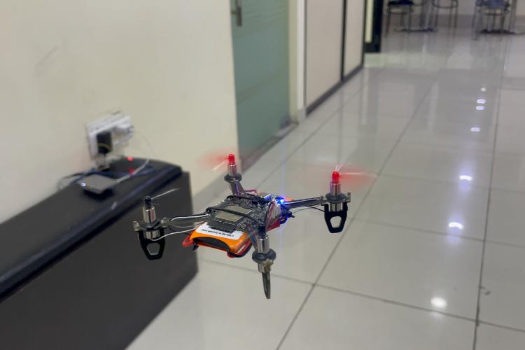
And here is the fully assembled drone.

The images below show all the important parts marked on the drone.

Motor Rotation & Propeller Direction Configuration
Install A and B propellers according to the figure below. During the power-on self-test, check if the propellers spin properly and are spinning in the correct direction. The ESP32 drone flight controller uses a standard quadcopter X-configuration where diagonal motors rotate in the same direction.

| Motor Position | Rotation Direction | Propeller Type | GPIO Pin |
| Front Right (M1) | Clockwise (CW) | Standard | GPIO 32 |
| Front Left (M2) | Counter-Clockwise (CCW) | Reverse | GPIO 26 |
| Rear Left (M3) | Clockwise (CW) | Standard | GPIO 25 |
| Rear Right (M4) | Counter-Clockwise (CCW) | Reverse | GPIO 27 |
ESP32 Drone Code and Firmware Programming
Programming the ESP32 drone controller requires either building from source using ESP-IDF or flashing pre-compiled firmware binaries. The firmware from our DIY drone is based on the ESP-drone firmware from Espressif. The code is written with ESP-IDF, and the version that is used to compile this code is ESP-IDF 4.4.5. Follow the following link to install and configure ESP32 IDF version 4.4.5. You can either build the firmware from scratch using the source provided at the GitHub repo below, or you can just flash the binary file provided within the same repo if you don’t want the hassle. Make sure to use the source code provided on GitHub below, because there are many modifications to Espressif’s code to suit our PCB design.
Three Methods to Flash ESP32 Drone Firmware
To flash the code on our ESP32 Drone, you can follow any one of the three methods below.
⇒ Method 1: Building from Source using ESPIDF
To start with, install and configure ESP-IDF. Please follow the detailed instructions from Espressif. Make sure to install version 4.4.x of ESP-IDF.
Once the ESP-IDF is installed, clone the ESP-Drone firmware repo using git and navigate to the firmware folder.
git clone https://github.com/Circuit-Digest/ESP-Drone.git
cd ESP-Drone/Firmware/esp-drone
You can change all the firmware configurations using menuconfig. For our use case, the current configuration is enough, and you don’t need to change anything.
idf.py menuconfigNow, to build and flash the firmware, you can use the flash command. It will automatically build and flash the project. Replace PORT with your ESP32-S2 board’s serial port name.
idf.py -p PORT flash⇒ Method 2: Using ESPTOOL
To use the ESPtool, make sure you have installed the ESP IDF. You can find the instructions for that in the previous section. Once installed and configured, open the terminal in the same folder as the firmware image and use the following command to flash the firmware.
esptool.py write_flash --flash_size detect 0x0 ESPDrone.bin⇒ Method 3: Using ESP32 Flash Download Tool
First, download the ESP32 Flash Download Tool
Extract it to a folder and double-click on the .exe file to run it. When prompted, select ESP32 in the chip type field and click on OK.
Select the firmware file with the ESPDrone.bin file and add the address as 0x00. Select the proper COM port and click on erase. Once the flash erase is complete, click on START to flash the firmware
That's it. You are ready to use your DIY drone.
Using The Drone
Place the drone on a flat surface and turn it on. As soon as it’s turned on, the flight controller will create a Wi-Fi hotspot. Connect to it using the password 12345678 and open the app. For the IOS, the app can be downloaded from the App Store, just search for ESP-Drone APP. For Android, you can download the app from the following link. Keep in mind that the app is created and hosted by a third party. So, install them at your own will. The app interface will look like this.
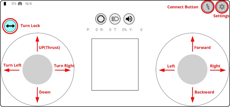
Click on the connect button to start communicating with the drone. When the connection is established successfully between your drone and the APP, the LED on the drone blinks GREEN. The turn lock button can be used to lock the left controller for just up and down, or up, down, left turn and right turns. Use the left stick to take off or land the drone. Use the right stick to control the movements. If the drone disconnects from the app or the drone itself is rebooting when trying to take off, that means the battery can’t provide enough power. We have used a 1300mAh 30C battery. So, please ensure to use a battery with a higher discharge rating.
Preflight Check
- Place the drone with its head on the front, and its tail (i.e., the antenna part) at the back.
- Place the drone on a level surface and power it up when the drone is still.
- After the communication is established, check if the LED on the drone's tail blinks GREEN fast.
- A blinking RED LED indicates battery LOW. Charge the battery if it happens.
- Slide the Trust controller forward slightly to check if the drone can respond to the command.
- Use the right controller to check if the direction control works well.
ESP32 Drone GitHub Repository
The complete source code for this ESP32 drone project is available on Circuit Digest's GitHub repository, which includes comprehensive documentation, build instructions, and example configurations, via the following link.


This project was designed and tested by the Circuit Digest engineering team to demonstrate practical applications of WiFi control in drones using Arduino and ESP8266. Our experts focus on creating practical, hands-on tutorials that help makers and engineers master Raspberry Pi projects, Arduino projects, ESP32 Projects and IoT development projects.
I hope you liked this article and learned something new from it. If you have any doubts, you can ask in the comments below or use our forum for a detailed discussion.
Frequently Asked Questions on the ESP32 Drone Project
⇥ Can an ESP32 drone be equipped with a camera for photography?
Definitely! Small action cameras and ESP32-CAM modules are among the lightweight cameras (20–50g) that ESP32 drones can transport.
⇥ Why Choose ESP32 over Arduino for Drone Projects?
In comparison to Arduino, the ESP32 provides WiFi connectivity, dual-core processing, and superior performance for drone applications.
⇥ Does building an ESP32 drone require programming experience?
While not necessary, basic programming is helpful. There is pre-written code available, and a tutorial guide for beginners with step-by-step explanations.
⇥ What is the expected range of flight time for an ESP32 drone on one battery?
If you are flying with a 1300mAh 30C 1S LiPo battery, you should expect about 5-7 minutes of flight per charge. Flight time varies with style (aggressive flying, hovering), discharge rates, weight of the drone, and motor efficiency. Also, a 1500-2000mAh battery will give you a range of 7-10 minutes.
⇥ Can the ESP32 drone be flown outdoors, or do you have to only fly it inside?
The ESP32 drone can fly outdoors or indoors in calm weather conditions. However, it is very lightweight (total weight is around 60 grams) and will be susceptible to drifting in light wind above 5-8 mph. Without GPS, it cannot hold its position outdoors and will drift in line with the wind. It flies the best when the wind is lightest, especially on a morning or evening when the winds have stopped.
⇥ What is the WiFi range of an ESP32 drone controller?
Standard WiFi range is 30-50 meters in open air and 15-25 meters indoors, subject to interference and obstacles. The ESP32's 2.4GHz antenna ensures strong communication in this range. For long-range, you can try adding an external antenna or going for LiteWing firmware, which allows long-range communication protocols.
⇥ How do I debug an ESP32 drone if it does not fly very stably?
Normal stability issues occur with: propeller on wrong orientation (check CW and CCW), IMU not calibrated (rescale your MPU6050 over a flat surface), battery is dead (ensure a battery that discharges at 30C+), loose wiring to motors, or wrong PID tuning. Always do the preflight checklist and test for motor response before flight. The troubleshooting guide in the GitHub repository can be referred to.
Projects related to ESP32: Gesture-controlled drone and LiteWing tutorials.
Learn to build and program ESP32-powered drones with LiteWing and Python. This collection covers gesture control, height hold mode, and core flight customisation techniques for hands-on experimentation and development.

DIY Gesture Control Drone using Python with LiteWing and ESP32
In this article, we are going to show you how you can build a gesture control drone. To do this, we will obviously need a drone, which in our case is a LiteWing Drone, and to control this drone, we will use an ESP32 dev module along with an MPU6050, both of which are strapped to our hand.

LiteWing - ESP32-Based Programmable Drone for Makers, Developers and Educators
LiteWing is a compact, WiFi-controlled drone based on the ESP32-S3 microcontroller. Designed for hobbyists, makers, and engineers, LiteWing offers a simple yet powerful platform for drone experimentation and development

How to Use Height Hold Mode in LiteWing ESP32 Drone?
If you're building your LiteWing from scratch, you can check out our detailed step-by-step LiteWing assembly guide to get started with your build. This is where Drone height hold mode becomes a game-changer for drone pilots of all skill levels.
Comments
Check your IMU. If the IMU is not connected properly or is faulty, the drone won't be ready to fly.
Hello
My drone not get action from mobile app, how u can fix it?
Hi, could you send me the measurements in cm so I can make the pieces to 3D print or if you have already made them, could you send them to me, thank you very much.
I am using modules for every part of the drone instead of IC, but I have connected everything as per the schematics, After the code is written on the esp32 D0WD v3 (revosion3) aka esp32 devkit v1, it checks for wifi , it goes green , but the "I2C connection to MPU6050 always fails, I have checked for pin connections and even checked the MPU6050 alone for any defects but it works just fine, but always fails in this system. do let me know what i can do. (pins used GPIO21 and GPIO22 for SDA & SCL respectively) also tried to connect the INT pin to GPIO14 yet it does not work

during flashing of firmware it stops after
I (6522) SYSLOAD: 2.25 1492 ipc1 24
I (6527) SYSLOAD: Free heap: 88332 bytes
and stuck after this