
In this project we are going to build a Digital Voltmeter without using any microcontroller. Here we are using a very popular IC for voltage measurement namely ICL7107/CS7107. Using ICL7107, we can build accurate and very low cost voltmeter. ICL7107 is a 3.5 digit analog to digital converter (ADC) which consumes very low power. The IC has internal circuit for driving four seven segment display to display the measured voltage. It also has a clock circuit and a reference voltage source.
Voltmeter is very useful device and comes very handy many times, that’s why we have built this Digital Voltmeter on PCB so that it can be used anywhere easily. Previously we have built many circuits for measuring the Voltage:
- 0-25V Digital Voltmeter using AVR Microcontroller
- LM3914 Voltmeter Circuit
- PIC Based Car Battery Voltage Monitoring System
- Battery Monitor Circuit
Components Required:
- LM555 -1
- ICL7107/CS7107 -1
- LM7805 -1
- Common anode Seven segments LED display -4
- PCB -1
- Terminal Block 2 pin -2
- 47k -1
- 1k -5
- 22k -1
- 10K -1
- 120K -1
- POT 5K -1
- 100nF -3
- 10uF -2
- 100pF -1
- 220nF -1
- 47nF -1
- Power Supply 9v/12v -1
- LED -1
- Berg sticks -2
- 40 pin IC base -1
- 8 pin IC base -1
- Probe or wire
- 1N4148 Diode -2
Circuit Diagram and Working Explanation:
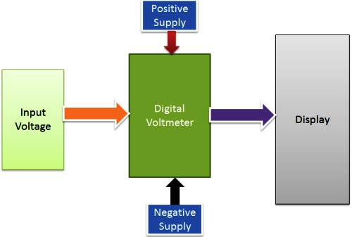
Working of this Digital Voltmeter Circuit is very simple. ADC inside the IC is integrating converter or Dual type Analog to digital converter. Internal ADC of this IC reads the voltage that to be measured and compare it with an internal reference voltage and converts that into the digital equivalent. Then this digital equivalent is decoded for Seven Segment Displays by driver circuit inside ICL7107 and then displayed over Four seven segments LED display. Learn here how a ADC can be used to measure Voltage and check the Demonstration Video the end of this article, where we have measured the Arduino output power for testing purpose.

Here resistor R1 and capacitor C1 are used to set the frequency of internal clock of ICL7107. Capacitor C2 filters the fluctuations in internal reference voltage and provides stable reading on seven segment displays. R5 is responsible for controlling the range of the voltmeter. (R5=1K for 0-20V range and 10K for 0-200V range). RV1 is a potentiometer which may be used for calibrating the voltage of voltmeter or can be set the reference voltage for internal ADC.
This circuit includes 4 Common Anode Seven Segment LED Displays with a negative voltage indicator. This circuit should be operated at 5V voltage supply, that’s why we have used a 7805 voltage regulator IC to supply 5v to the circuit as well as for preventing the damage of ICL7107.
Negative Voltage Supply: Here we have also need to give negative power to pin number 26 of the ICL7107, for which we have used 555 IC. The 555IC timer IC is configured here as ASTABLE multivibrator. The capacitor here can be changed however the selection should pursued for maximum negative voltage. If selected capacitance does not suit well, then we cannot get maximum negative voltage at the output. Here we have used 100nF and 10uF. Check here how we can use 555 Timer IC to generate Negative Voltage.
Circuit and PCB Design using EasyEDA:
EasyEDA is not only the one stop solution for schematic capture, circuit simulation and PCB design, they also offer a low cost PCB Prototype and Components Sourcing service. They recently launched their component sourcing service where they have a large stock of electronic components and users can order their required components along with the PCB order.
While designing your circuits and PCBs, you can also make your circuit and PCB designs public so that other users can copy or edit them and can take benefit from there, we have also made our whole Circuit and PCB layouts public for this Digital Voltmeter using ICL7071, check the below link:
https://easyeda.com/circuitdigest/Voltmeter-68b3b31dc1d548a4954d55b24f77110e
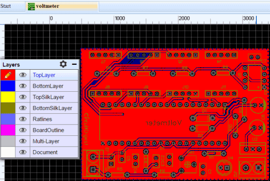
Below is the Snapshot of Top layer of PCB layout from EasyEDA, you can view any Layer (Top, Bottom, Topsilk, bottomsilk etc) of the PCB by selecting the layer form the ‘Layers’ Window.
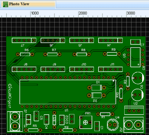
You can also see Photo view of PCB using EasyEDA:
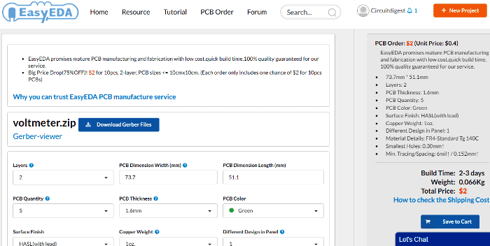
Calculating and Ordering Samples online:
After completing the design of PCB, you can click the icon of Fabrication output, which will take you on the PCB order page. Here you can view your PCB in Gerber Viewer or download Gerber files of your PCB. Here you can select the number of PCBs you want to order, how many copper layers you need, the PCB thickness, copper weight, and even the PCB color. After you have selected all of the options, click “Save to Cart” and complete your order. Recently they have dropped their PCB rates significantly and now you can order 10 pcs 2-layer PCB with 10cm x 10cm size just for $2.
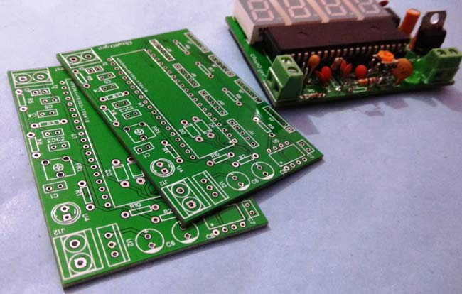
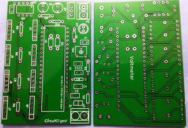
Here is the PCBs I Got from EasyEDA:
Below are the pictures after soldering the components on PCB:
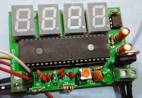
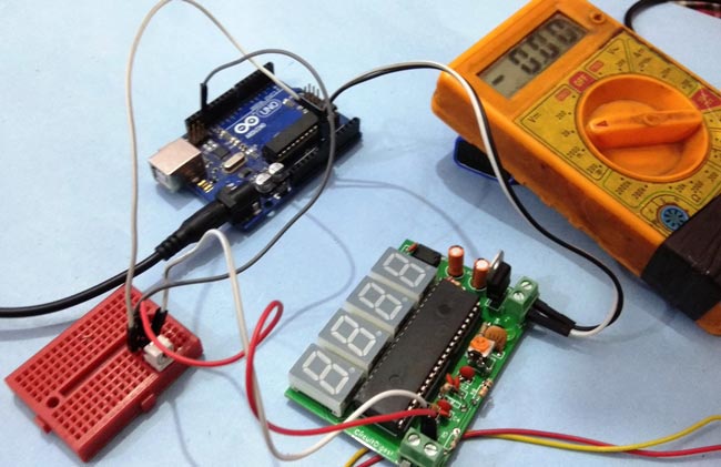
Here in this project we have measured the Arduino output voltage for testing purpose, check the Demo Video below.
Comments
You can buy gadgets with more features than the projects detailed in all electronics magazines / sites for a fraction of the cost from Chinese manufacturers. The underlying purpose of a project is not to save money, but to learn the working principles of these gadgets and gain some dexterity.
Building a project such as this can, indeed, be more costly than buying a cheap Chinese digital meter. One reason for building this project would be to modify it before building in such a way that more exactly suits your requirement, in a way that the off-the-shelf Ebay product can't be. You can build this project using components that give you much better accuracy than the Ebay products. You can modify the size and/or shape of this product to suit your own DIY project; something you can't do with the Ebay product. Or, there's always the idea of building something yourself, and seeing it work; just for the personal satisfaction.
Dave M
In the schematic, R5 is 1Meg but in the description, it says R5 should be 1k for 0 - 20v range and 10k for 0 - 200v range?
I have same design ckt of volt meter but the problem be is when I calibrate 5v =12.00 v the the meter reading will changes 0.10 v & it will slowly decresing reading , it's take 2 to 3 min for showing currect value what is the reasin
The problem is most likely with your Hardware. Use a multimeter to read what voltage is being read across the ADC pin. I think a capacitor is most likely the culprit
The C8 electrolytic capacitor is marked on theSchematic and on the PCB in reverse polarity. You have to reverse it for minus voltages.

Why would anyone build this voltmeter. I can buy a digital voltmeter on eBay for under $5.00 or get a DVM from Harbor Freight FREE!