

In electronics, waveforms are mostly plotted against voltage and time. The frequency and amplitude of the signal can vary according to the circuit. There are many types of waveforms, like sine wave, square wave, triangular wave, ramp wave, sawtooth wave etc. We have already designed sine wave and square wave generator circuit. Now, in this tutorial we will show you, how to design a sawtooth wave generator circuit with adjustable gain and DC offset of the wave, using Op-amp and 555 timer IC.
A Sawtooth waveform is a non-sinusoidal waveform, looks similar to a triangular waveform. This waveform is named sawtooth because it looks similar to the teeth of a saw. Sawtooth waveform is different from triangular waveform because a triangular wave have same rising and falling time while a sawtooth waveform rises from zero to its maximum peak value and then quickly drops to zero.
Sawtooth waveform is used in filters, amplifier circuits, signal receivers etc. It is also used for tone generation, modulation, sampling etc. An ideal Sawtooth waveform is shown below:

Material Required
- Op-amp IC (LM358)
- 555 Timer IC
- Oscilloscope
- Transistor (BC557 – 1nos.)
- Potentiometer (10k – 2nos.)
- Resistor
- 4.7k – 1nos.
- 10k – 3nos.
- 22k – 3nos.
- 100k – 3nos.
- Capacitor (0.1uf, 1uf, 4.7uf, 10uf – 1nos. each)
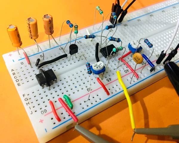
- Breadboard
- 9V power supply (Battery)
- Jumping Wires
Circuit Diagram

Working of Sawtooth Generator Circuit
For generating a sawtooth waveform we have used 555 timer IC and LM358 Dual Op-amp IC. In this circuit, we are using transistor T1 as a controlled current source with adjustable emitter and collector current. Here the 555 Timer IC is used in astable mode.
The resistor R2 and R3 set up a bias voltage for biasing the base pin of the PNP transistor T1. And, R1 is used for setting the emitter current which effectively sets the collector current, and this constant current charges the capacitor C1 in a linear way. That’s why we receive a ramp output. By replacing R1 with a potentiometer you can adjust the ramp speed.
By shorting the trigger, discharge and threshold pin of the 555 timer directly with the capacitor C1, this allows the capacitor to charge and discharge.
Here, the first op-amp O1 is working as a level shifting inverting buffer. As it’s an inverting buffer the lower portion of the ramp will become the upper portion of the inverted ramp.
Then, the output of this Op-amp is attached with the POT P1, which is used to adjust the magnitude of the signal. Similarly, Op-amp O2 is used to adjust the DC offset of the signal. And, the output is taken form the output terminal of the Op-amp O2.
The first probe of the oscilloscope is connected to this output and the second probe is connected to the trigger pulse, which is coming from the output terminal of the 555 timer IC. So after connecting both the probes of the oscilloscope, the output of the sawtooth waveform will look as the image given below:
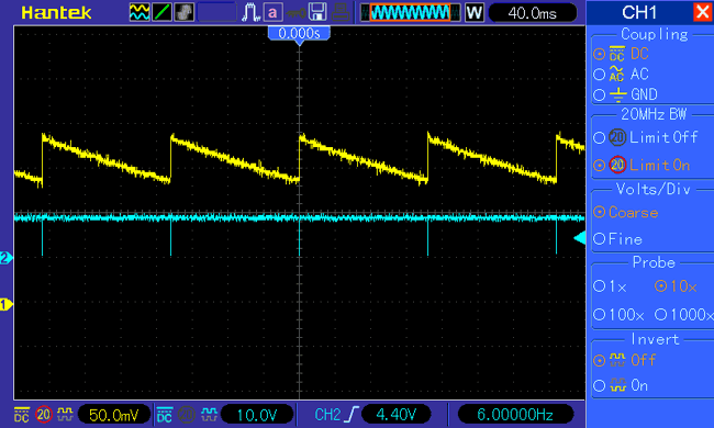
To adjust the gain and DC offset of the signal move potentiometer P1 and P2 respectively.
