

Vending machines are very popular nowadays due to their ease of use, multiple use cases, and no human intervention. It can dispense products such as beverages, tickets, snacks, etc. by inserting currency coins. Vending machines appear in public and private areas such as malls, markets, offices, etc. for various applications. In this project, we are going to build a Portable Drinking Water vending machine using Arduino which can be used in any public places such as tourism places to dispense drinking water or any other beverage using Currency coins. This Vending machine uses a single Coin Acceptor Module that accepts the currency coins, and TRIAC, and Optocoupler circuitry are used to dispense the water.
Components Required for Building a Drinking Water Vending Machine:
- Arduino UNO
- Coin Acceptor Module
- BT136 TRIAC
- MOC3021 Optocoupler
- Dot Matrix Perf Board
- Connecting Wires
- LED
- 230V AC Water Pump
- Pipes & Fitting
Drinking Water Vending Machine Working
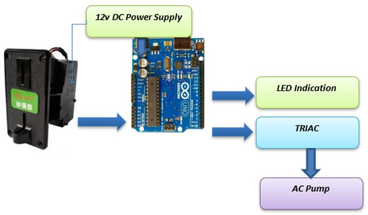
As shown in the block diagram above, the Coin acceptor module acts as the input device which gives the signal to Arduino when it detects a valid Coin inserted within it. Arduino receives the signal and gives the digital command to Opto isolator which triggers the TRIAC to switch ON/OFF the Water Pump for a specific duration. Similarly, a LED is connected to indicate the dispensing action.
Coin Acceptor Module Working
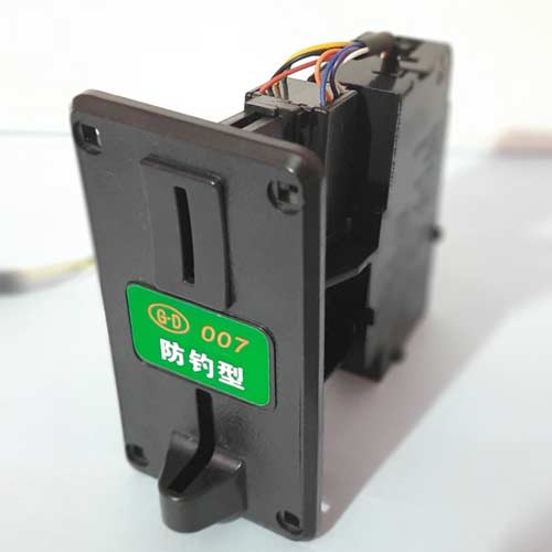
Coin acceptor modules accept currency coins which can be suitable for various vending machines. Coin acceptor modules are available in multiple categories including single coin acceptor, comparable type coin acceptor, multi-coin coin acceptor, etc. The Single coin acceptor is specially designed to accept only a specific coin. A comparable type of coin acceptor is used to accept the coins that are similar to the coins put aside the coin acceptor. Multi-coin coin acceptors can accept different coins with one machine, and output different signals to the microcontroller. In this project, a single coin acceptor is used.
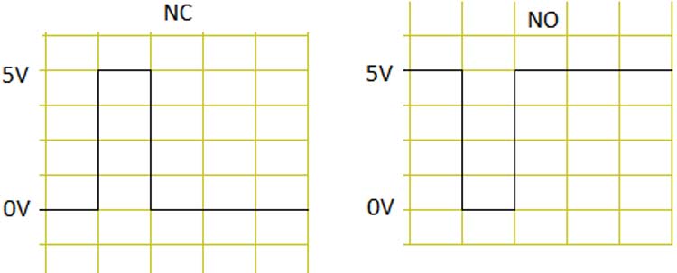
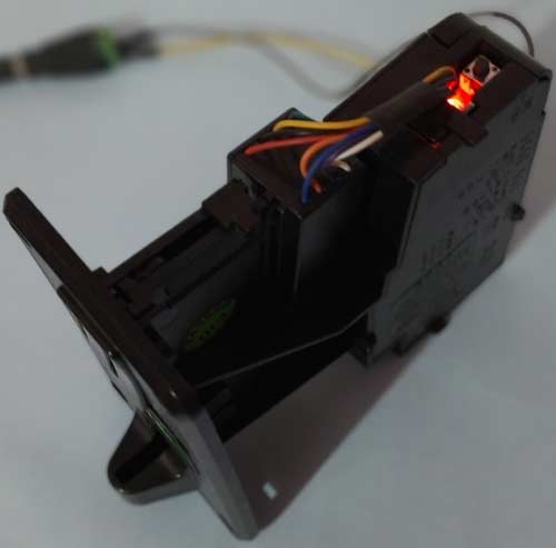
The coin accepting device has an inbuilt microcontroller that takes data from the sensor inside the device and collects different coins. Using this data, the microcontroller knows whether this coin needs to be accepted or returned. The device is easily programmed using a push-button located on the top. The coin acceptor device gives us an impulse signal on the output pin for every inserted coin and by counting impulses we know how many coins have been inserted. It also has three switches which we use in order to select the type of signal we want to get on the output. The first switch has three positions to select the impulse length. The second switch is used to set the signal to be +5 V(NC) or 0 V(NO) as shown in the figure. Using the 3rd switch, the precision of the device can be chosen.
Training of Coin Acceptor Module
To train the Module for a specific coin, follow the steps below:
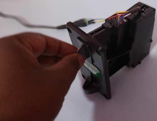
- First, press the push button located on the top and hold it for 4-5 seconds until the RED LED glows up, and then release it.
- While the RED LED is on, insert the coin we want to program it for. For example, if we want to program it for 2 Rupees coins, then we will insert only 2 Rupees coins while we program it.
- Insert the same coin into the device 30 times in order to train the coin to memory. After the programming is over, the LED will turn off and the device is ready for use.
TRIAC Circuit Working
TRIAC is a three-terminal AC switch that can be triggered by a low-energy signal at its gate terminal. In SCRs, it conducts in only one direction, but in the case of TRIAC, the power can be controlled in both directions. Here BT136 TRIAC is used for AC Pump Switch ON/OFF purposes.

As shown in the figure above, the TRIAC is triggered at a firing angle of 90 degrees by applying a small gate pulse signal to it. The time “t1” is the delay time which we have to give as per our application requirement. For example, in this case, as the firing angle is 90 percent, hence the average power output will be halved. In case we want to turn ON the device, we need to switch it ON completely i.e t1=0.
Optocoupler
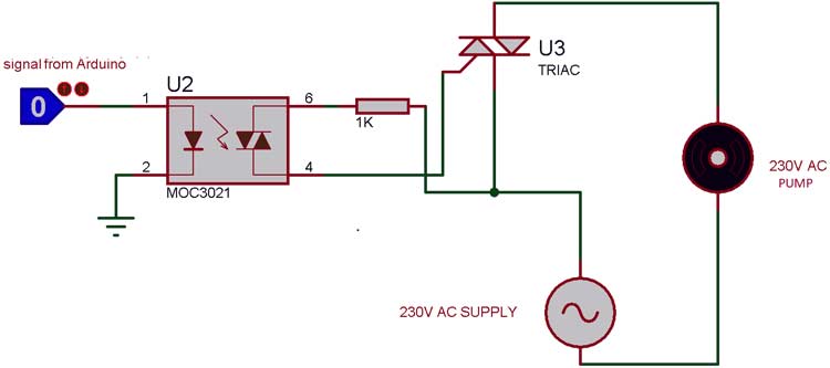
Optocoupler is also known as Optoisolator. It is used to maintain isolation between two electrical circuits like DC and AC signals. Basically, it consists of a LED that emits infrared light and a photosensor that detects it. Here MOC3021 optocoupler is used to control the AC Pump from our microcontroller signals which is a DC signal.
Drinking Water Vending Machine Circuit Diagram

TRIAC and Optocoupler Connection Circuit Diagram
Programming Arduino for Vending Machine
Here we are going to program Arduino to detect the coin insertion and coin type. Upon successful detection, it will turn on the Pump to dispense water. Complete code is given at the end of the document. Here, in the below lines we are explaining the important parts of the code.
First, define the pins which are used in the hardware as shown below. Digital Pin 2 is used as an input interrupt pin and Digital pin 6 & 12 are used for TRIAC & LED respectively.
const int COIN = 2;
const int TRIAC = 6;
const int LED=12;
boolean Coin_insert = false;
int count=0;
Next, inside the setup function, an external interrupt pin will be configured to detect the coin insertion in the device. Here a function called attachInterrupt is used, which will configure digital Pin 2 of Arduino as an external interrupt and it will call the function named coinInterrupt, when it detects any interrupts at its pin.
void setup() {
  Serial.begin(9600);
  attachInterrupt(digitalPinToInterrupt(COIN), coinInterrupt, RISING);
  pinMode(TRIAC, OUTPUT);
  pinMode(LED, OUTPUT);
}
Inside Loop(), the coin insert status is checked and if it detects successful coin insertion, then the TRIAC is triggered for a specific duration to switch on the Pump to dispense water and after completion, it is triggered OFF.
void loop() {
  if(Coin_insert)  {
     digitalWrite(LED, HIGH);
     delay(1000);
     digitalWrite(TRIAC, HIGH);
     delay(12000);
     digitalWrite(TRIAC, LOW);
     delay(2000);
     Coin_insert = false;
  }
  else  {
     digitalWrite(LED, LOW);
     digitalWrite(TRIAC, LOW);
  }
}
Function coinInterrupt is called when the hardware interrupt is detected i.e. When the coin acceptor detects a valid coin.
void coinInterrupt() {
    Coin_insert = true;
}
Components Assembling and Testing
Now after connecting the components as per the circuit diagram and programming the Arduino let’s build an enclosure like a vending machine with a water storage tank as shown below.

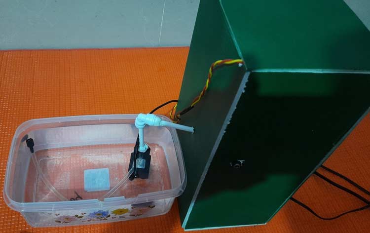
After assembling all units in an enclosure, the setup looks like below:
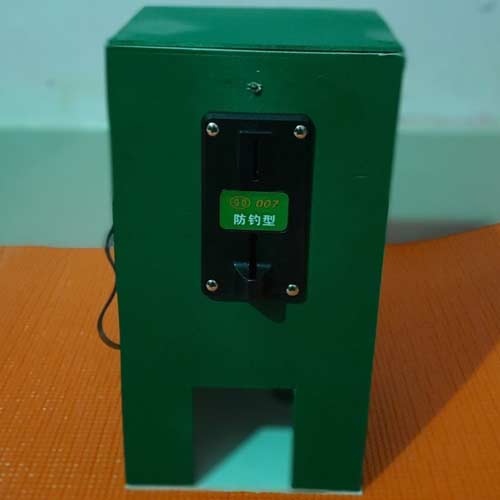
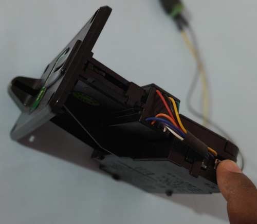
The backside view of the product looks like below.
To Test the Arduino Vending Machine, switch ON the power supply and place a Glass inside the tap to collect water. Now put a 2 rupees coin inside the acceptor. Once it detects the coin the Green LED should glow and water dispensing should start. Once the glass is filled, the LED and pump should turn OFF.
This is how you can build a Drinking Water Vending Machine Arduino and Coin Acceptor module. If you have any questions or suggestions, you can put them in the comment section or can use our forum.
Coin_Acceptor.ino
const int COIN = 2;
const int TRIAC = 6;
const int LED=12;
boolean Coin_insert = false;
int count=0;
void setup()
{
  Serial.begin(9600);
  attachInterrupt(digitalPinToInterrupt(COIN), coinInterrupt, RISING);
  pinMode(TRIAC, OUTPUT);
  pinMode(LED, OUTPUT);
}

void loop()
{
  if(Coin_insert)
  {
     digitalWrite(LED, HIGH);
     delay(1000);
     digitalWrite(TRIAC, HIGH);
     delay(12000);
     digitalWrite(TRIAC, LOW);
     delay(2000);
     Coin_insert = false;
  }
  else
  {
  digitalWrite(LED, LOW);
  digitalWrite(TRIAC, LOW);
  }
  }

void coinInterrupt()
{
 Coin_insert = true;
}
I really love this Project, please can i have more images on how you made this? i wanted to make this for my School Project. i would ve very grateful if you give me more tutorials for this project, Thank you.