
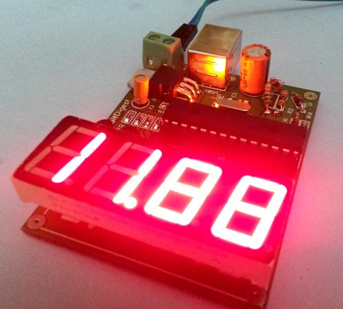
In this project we are going to make a PIC based Car Battery Monitoring system on PCB. Here we have designed a PCB using EASYEDA online PCB simulator and designer. This Car Battery Monitoring Circuit is used to monitor the power of Car Battery by just plugging it into the power outlet on the dashboard of a car. The PCB also has the option to use it as Voltage Measurement tool or Voltmeter without using USB car charger. We have attached a terminal block here to measure the voltage of other power sources, just by connecting two wires in it from the power source.
Components Required:
- PIC Microcontroller PIC18F2520 -1
- Fabricated PCB Board -1
- USB connector -1
- 2 pin Terminal Connector (optional) -1
- Common anode seven segment display(4 in 1) -1
- BC557 Transistor -4
- 1k resistor -6
- 2k resistor -1
- 100R resistor -8
- 1000uF capacitor -1
- 10uF capacitor -1
- 28 pin IC base -1
- female burgsticks -1
- 7805 Voltage regulator -1
- Car USB charger -1
- LED -1
- Zener diode5.1v -2
- USB cable (B-type or Arduino UNO compatible) -1
- 20MHz Crystal -1
- 33pF capacitor -2
Description:
Generally it is not important to measure the car battery power every time, but we often need to know about battery voltage during charging, to check whether its charging or not. By this, we can protect battery failure due to the faulty charging system. The voltage of a 12v car battery during charging is about 13.7v. So we can identify whether our battery is charging well or not and can investigate the causes of battery failure. In this project, we are going to implement a Voltage Meter for Car Battery by using a PIC microcontroller. Car Cigarette Lighter or Car USB charger is used for getting the battery voltage to the ADC pin of the microcontroller with the help of Voltage Divider Circuit. Then a 4 digit seven segment display is used to show the voltage value of battery. This circuit can measure the voltage up to 15v.
When a car battery is charging, then the voltage across the battery terminals is actually coming from the alternator/rectifier, that’s why system reads 13.7 volts. But when the battery is not charging or car’s engine is not ON, then the voltage across battery terminal is actual battery voltage around 12v.
We can also use the same circuit for measuring the voltage of other power sources up to 15v. For this purpose we have soldered the Terminal Block (green color plastic block) in PCB where you can connect two wires from power source and can monitor the voltage. Check the Video at the end, where were we have demonstrated it by measuring the voltage of a Variable power Supply, a USB power bank and a 12v AC-DC adapter. Also check the Simple Battery Monitor Circuit and 12v Battery Charger Circuit.
Circuit Diagram and Working Explanation:
In this Battery Voltage Monitoring Circuit, we have read car battery voltage by using an inbuilt analog pin of PIC microcontroller and here we have selected pin AN0 (28) pin of microcontroller through a voltage divider circuit. A zener diode of 5.1v is also used for protection.

4 in 1 seven segment display is used for displaying the instantaneous value of car battery voltage that is connected at PORTB and PORTC of the microcontroller. A 5v voltage regulator namely LM7805 is used to powering the whole circuit including Seven Segment Displays. A 20 MHz crystal oscillator is used to clock the microcontroller. Circuit is powered by the USB car charger itself by using a LM7805. We have added a USB port in the PCB, so we can directly connect car USB charger to the circuit.
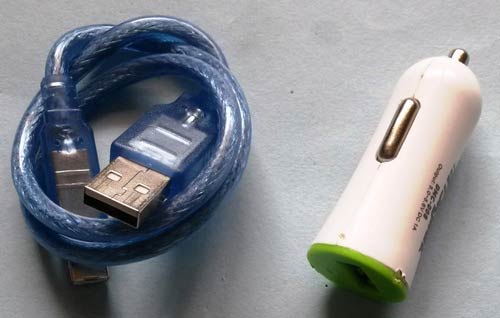
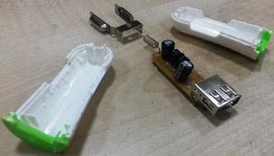
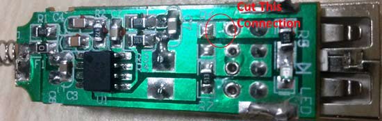
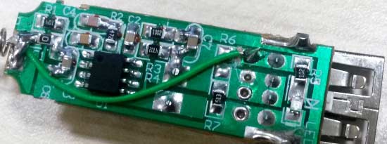
Car USB charger or Cigarette lighter provides 5v regulated supply from the 12v power outlet of the car, but we need to measure the actual voltage of Car battery so we have tweaked the Car charger. You need to open the car USB charger and then find the 5v (output) and 12v (input) terminals and then remove 5v connection by rubbing it with sand paper or with some hard thing and short the USB output terminal to 12v directly. First open the 5v connection from the USB port in the car USB charger and then connect 12v to the USB port where 5v was connected. As shown in below figure, we have cut the red circled connection, it may differ in your car charger.
To configure ADC here we have selected analog pin AN0 with an internal reference voltage of 5v and f/32 clock for ADC conversion.
To calculate car battery voltage from the ADC value we have used given formula:
Voltage= (ADC value / resistor factor) * reference Voltage
Where:
ADC value= output of Voltage divider (converted into digital by microcontroller)
Resistor factor = 1023.0 / (R2/R1+R2)        // 1023 is max ADC value (10-bit)
Reference Voltage= 5 volts                   // internal 5v reference selected
Resistor Factor Calculation:
In this project we are reading car battery voltage that is (generally) around 12v-14v. So we have done this project assuming max 15v means this system can be read max upto 15v.
So in the circuit we have used R1 and R2 resistor in voltage divider part and values are:
R1= 2K
R2=1K
Resistor factor= 1023.0 * (1000/2000+1000)
Resistor factor=1023.0 * (1/3)
Resistor factor= 341.0 for up to 15 volts
So Final Formula for voltage calculation will be as follow, which we have used the Code, given at the end of this Article:
Voltage= (ADC value / 341.0) * 5.0
Circuit and PCB Design using EasyEDA:
To design a Circuit for Car Battery Voltage Monitor, we have used EasyEDA which a free online EDA tool for creating circuits and PCBs in a seamless manner. We have previously ordered few PCBs from EasyEDA and still using their services as we found the whole process, from drawing the circuits to ordering the PCBs, more convenient and efficient in comparison of other PCB fabricators. EasyEDA offers circuit drawing, simulation, PCB design for free and also offers high quality but low price Customized PCB service. Check here the complete tutorial on How to use Easy EDA for making Schematics, PCB layouts, Simulating the Circuits etc.
EasyEDA is improving day by day; they have added many new features and improved the overall user experience, which makes EasyEDA easier and usable for designing circuits. They are soon going to launch its Desktop version, which can be downloaded and installed on your computer for offline use.
In EasyEDA, you can make your circuit and PCB designs public so that other users can copy or edit them and can take benefit from there, we have also made our whole Circuit and PCB layouts public for this Car Battery Voltage Monitor, check the below link:
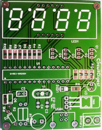
Below is the Snapshot of Top layer of PCB layout from EasyEDA, you can view any Layer (Top, Bottom, Topsilk, bottomsilk etc) of the PCB by selecting the layer form the ‘Layers’ Window.
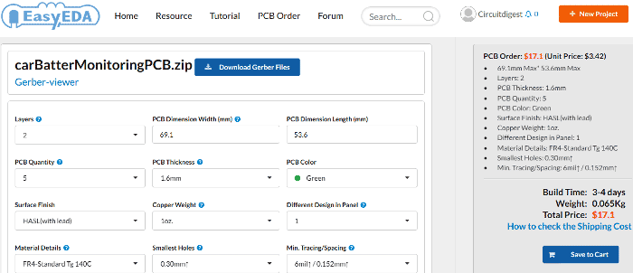
Calculating and Ordering PCB Samples online:
After completing the design of PCB, you can click the icon of Fabrication output, which will take you on the PCB order page. Here you can view your PCB in Gerber Viewer or download Gerber files of your PCB and send them to any manufacturer, it’s also a lot easier (and cheaper) to order it directly in EasyEDA. Here you can select the number of PCBs you want to order, how many copper layers you need, the PCB thickness, copper weight, and even the PCB color. After you have selected all of the options, click “Save to Cart” and complete you order, then you will get your PCBs a few days later.
You can directly order this PCB or download the Gerber file using this link.
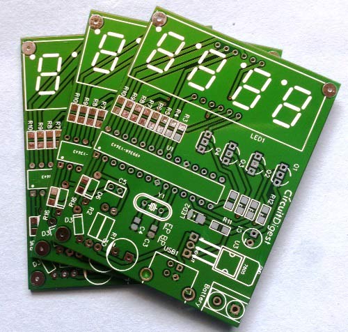
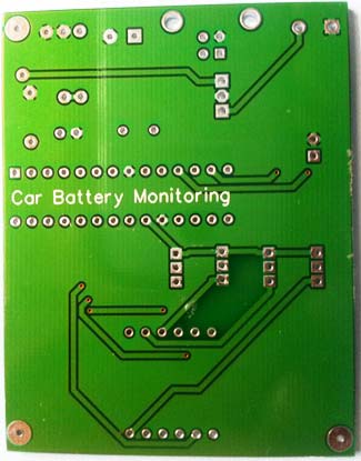
After few days of ordering PCB’s I got the PCB samples
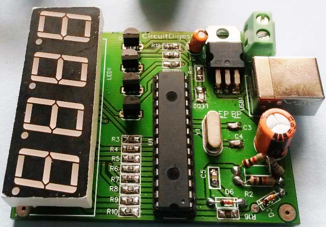
After getting the PCBs I have mounted all the required components over the PCB, and finally we have our Car Battery Monitoring System ready, check this circuit in working in Video given at the end.
Programming Explanation:
Program of this project is little difficult for beginners. To write this code we need some header files. Here we are using MPLAB X IDE for coding and XC compiler to build and compile the code. The code is written in C language.
In this code, we have read battery voltage using an analog pin and for controlling or sending data to 4-digit seven segment display, we have used Timer Interrupt Server Routine in PIC microcontroller. All the calculation for voltage measurement is done in the main program routine.
First, in the code we have included a header and then configured PIC microcontroller using configuration Bits.
#include<xc.h>        //xc8 is compiler

// CONFIG1H
#pragma config OSC = HS
#pragma config FCMEN = OFF
#pragma config IESO = OFF

// CONFIG2L
#pragma config PWRT = ON
#pragma config BOREN = SBORDIS
#pragma config BORV = 3

// CONFIG2H
#pragma config WDT = OFF
#pragma config WDTPS = 32768
.... .....
..... .....
And then declared variables and defined pins for seven segments display
unsigned int counter2;
unsigned char position = 0;
unsigned char k[10]={0xc0,0xf9,0xa4,0xb0,0x99,0x92,0x82,0xf8,0x80,0x90};
int digit1=0,digit2=0,digit3=0,digit4=0;

#define   TRIS_seg1   TRISCbits.TRISC0
#define   TRIS_seg2   TRISCbits.TRISC1
#define   TRIS_seg3   TRISCbits.TRISC2
#define   TRIS_seg4   TRISCbits.TRISC3
#define   TRIS_led1  TRISAbits.TRISA2
#define   TRIS_led2  TRISAbits.TRISA5
#define   TRIS_led3  TRISAbits.TRISA0
#define   TRIS_led4  TRISAbits.TRISA1
#define   TRIS_led5  TRISAbits.TRISA
.... ....
..... .....
Now we have created a timer interrupt routine for driving seven segment display:
void interrupt low_priority LowIsr(void)
{
if(TMR0IF == 1)
{
   counter2++;
   if(counter2>=1)
   {

   if(position ==0)
    {
    seg1=0;
    seg2=1;
    seg3=1;
    seg4=1;
    .... ....
    ..... .....
Now in void main() function, we have initialized timer and interrupt.
GIE    = 1;                //GLOBLE INTRRUPT ENABLE
PEIE   = 1;                //peripheral intrupt flag
T0CON  = 0b000000000;      //prescaler value put
TMR0IE = 1;                //interrupt enable
TMR0IP = 0;                   //interrupt priority
TMR0   = 55536;            //start counter after this value
TMR0ON = 1;
And then in while loop, we read analog input at the analog pin and call some function for calculations.
while(1)
{
    adc_init();
    for(i=0;i<40;i++)
    {
        Value[i]=adc_value();
        adcValue+=Value[i];
    }
    adcValue=(float)adcValue/40.0;
    convert(adcValue);
    delay(100);
}
Given adc_init() function is used for initializing ADC
void adc_init()
{
    ADCON0 = 0b00000011;     //select adc channel
    ADCON1 = 0b00001110;     //select analog and digital i/p
    ADCON2 = 0b10001010;     //eqisation time holding cap time
    ADON   = 1;
}
Given adc_value function is used to read input from the analog pin and calculate voltage.
float adc_value(void)
{
float adc_data=0;
while(GO/DONE==1);                   //higher bit data start conversion adc value
adc_data = (ADRESL)+(ADRESH<<8);     //Store 10-bit output
adc_data =((adc_data/342.0)*5.0);
return adc_data;
}
And given convert function is used to convert voltage value to segment supported values.
 void convert(float f)
 {
     int d=(f*100);
     digit1=d%10;
     d=d/10;
     digit2=d%10;
     d=d/10;
     digit3=d%10;
     digit4=d/10;
 }
Check the Complete code for this project below with a demonstration Video.
Complete Project Code
#include<xc.h>        //xc8 is compiler
// CONFIG1H
#pragma config OSC = HS         // Oscillator Selection bits (HS oscillator)
#pragma config FCMEN = OFF      // Fail-Safe Clock Monitor Enable bit (Fail-Safe Clock Monitor disabled)
#pragma config IESO = OFF       // Internal/External Oscillator Switchover bit (Oscillator Switchover mode disabled)
// CONFIG2L
#pragma config PWRT = ON       // Power-up Timer Enable bit (PWRT disabled)
#pragma config BOREN = SBORDIS  // Brown-out Reset Enable bits (Brown-out Reset enabled in hardware only (SBOREN is disabled))
#pragma config BORV = 3         // Brown Out Reset Voltage bits (Minimum setting)
// CONFIG2H
#pragma config WDT = OFF        // Watchdog Timer Enable bit (WDT disabled (control is placed on the SWDTEN bit))
#pragma config WDTPS = 32768    // Watchdog Timer Postscale Select bits (1:32768)
// CONFIG3H
#pragma config CCP2MX = PORTC   // CCP2 MUX bit (CCP2 input/output is multiplexed with RB1)
#pragma config PBADEN = OFF     // PORTB A/D Enable bit (PORTB<4:0> pins are configured as digital I/O on Reset)
#pragma config LPT1OSC = OFF    // Low-Power Timer1 Oscillator Enable bit (Timer1 configured for higher power operation)
#pragma config MCLRE = ON       // MCLR Pin Enable bit (MCLR pin enabled; RE3 input pin disabled)
// CONFIG4L
#pragma config STVREN = ON      // Stack Full/Underflow Reset Enable bit (Stack full/underflow will cause Reset)
#pragma config LVP = OFF        // Single-Supply ICSP Enable bit (Single-Supply ICSP disabled)
#pragma config XINST = OFF      // Extended Instruction Set Enable bit (Instruction set extension and Indexed Addressing mode disabled (Legacy mode))
// CONFIG5L
#pragma config CP0 = OFF        // Code Protection bit (Block 0 (000800-001FFFh) not code-protected)
#pragma config CP1 = OFF        // Code Protection bit (Block 1 (002000-003FFFh) not code-protected)
#pragma config CP2 = OFF        // Code Protection bit (Block 2 (004000-005FFFh) not code-protected)
#pragma config CP3 = OFF        // Code Protection bit (Block 3 (006000-007FFFh) not code-protected)
// CONFIG5H
#pragma config CPB = OFF        // Boot Block Code Protection bit (Boot block (000000-0007FFh) not code-protected)
#pragma config CPD = OFF        // Data EEPROM Code Protection bit (Data EEPROM not code-protected)
// CONFIG6L
#pragma config WRT0 = OFF       // Write Protection bit (Block 0 (000800-001FFFh) not write-protected)
#pragma config WRT1 = OFF       // Write Protection bit (Block 1 (002000-003FFFh) not write-protected)
#pragma config WRT2 = OFF       // Write Protection bit (Block 2 (004000-005FFFh) not write-protected)
#pragma config WRT3 = OFF       // Write Protection bit (Block 3 (006000-007FFFh) not write-protected)
// CONFIG6H
#pragma config WRTC = OFF       // Configuration Register Write Protection bit (Configuration registers (300000-3000FFh) not write-protected)
#pragma config WRTB = OFF       // Boot Block Write Protection bit (Boot block (000000-0007FFh) not write-protected)
#pragma config WRTD = OFF       // Data EEPROM Write Protection bit (Data EEPROM not write-protected)
// CONFIG7L
#pragma config EBTR0 = OFF      // Table Read Protection bit (Block 0 (000800-001FFFh) not protected from table reads executed in other blocks)
#pragma config EBTR1 = OFF      // Table Read Protection bit (Block 1 (002000-003FFFh) not protected from table reads executed in other blocks)
#pragma config EBTR2 = OFF      // Table Read Protection bit (Block 2 (004000-005FFFh) not protected from table reads executed in other blocks)
#pragma config EBTR3 = OFF      // Table Read Protection bit (Block 3 (006000-007FFFh) not protected from table reads executed in other blocks)
// CONFIG7H
#pragma config EBTRB = OFF      // Boot Block Table Read Protection bit (Boot block (000000-0007FFh) not protected from table reads executed in other blocks)
#define   TRIS_seg1   TRISCbits.TRISC0
#define   TRIS_seg2   TRISCbits.TRISC1
#define   TRIS_seg3   TRISCbits.TRISC2
#define   TRIS_seg4   TRISCbits.TRISC3
#define   TRIS_led1  TRISAbits.TRISA2
#define   TRIS_led2  TRISAbits.TRISA5
#define   TRIS_led3  TRISAbits.TRISA0
#define   TRIS_led4  TRISAbits.TRISA1
#define   TRIS_led5  TRISAbits.TRISA4
#define   TRIS_PORTB      TRISB
#define  TRIS_adcpin      TRISAbits.TRISA0
#define  adcpin          PORTAbits.RA0
#define  TRIS_dot      TRISBbits.TRISB7
#define  dot          PORTBbits.RB7
#define seg1 PORTCbits.RC0
#define seg2 PORTCbits.RC1
#define seg3 PORTCbits.RC2
#define seg4 PORTCbits.RC3
#define led1  PORTAbits.RA2
#define led2  PORTAbits.RA5
#define led3  PORTAbits.RA0
#define led4  PORTAbits.RA1
#define led5  PORTAbits.RA4
void delay(unsigned long Delay)
{
    int i,j;
    for(i=0;i<Delay;i++)
        for(j=0;j<1000;j++);
}
void  adc_init();
float  adc_value(void);
void convert(float);
unsigned int counter2;
unsigned char position = 0;
unsigned char k[10]={0xc0,0xf9,0xa4,0xb0,0x99,0x92,0x82,0xf8,0x80,0x90};
int digit1=0,digit2=0,digit3=0,digit4=0;
/*************************************timer0*******************************************/
void interrupt low_priority LowIsr(void)
{
if(TMR0IF == 1)
{
   counter2++;
   if(counter2>=1)
   {
   if(position ==0)
    {
    seg1=0;
    seg2=1;
    seg3=1;
    seg4=1;
    }
    if(position ==1)
    {
    seg1=1;
    seg2=0;
    seg3=1;
    seg4=1;
    }
    if(position==2)
    {
     dot=0;
    seg1=1;
    seg2=1;
    seg3=0;
    seg4=1;
    }
 if(position==3)
    {
    seg1=1;
    seg2=1;
    seg3=1;
    seg4=0;
 }
    if(position == 0)
        PORTB = k[digit1];
    if(position == 1)
        PORTB = k[digit2];
    if(position == 2)
    {
        PORTB = k[digit3];
        PORTB&=~(0x80);
    }
    if(position == 3)
        PORTB = k[digit4];
    position++;
    if(position>=4)
        position = 0;
    counter2 =0;
   }
    TMR0 =55536;
    TMR0IF=0;
}
}
void main()
{
    float adcValue=0;
    float Value[40];
    int i=0;
ADCON1  = 0b00001111;      //all port is digital
GIE    = 1;                //GLOBLE INTRRUPT ENABLE
PEIE   = 1;                //peripheral intrupt flag
T0CON  = 0b000000000;      //prescaler value put
TMR0IE = 1;                //interrupt enable
TMR0IP = 0;                   //interrupt priority
TMR0   = 55536;            //start counter after this value
TMR0ON = 1;
TRIS_seg1   =0;
TRIS_seg2   =0;
TRIS_seg3   =0;
TRIS_seg4   =0;
TRIS_led1   = 0;
TRIS_led2   = 0;
TRIS_led3   =0;
TRIS_led4   =0;
TRIS_led5   =0;
TRIS_PORTB    = 0;
TRIS_adcpin    = 1;
TRIS_dot    = 0;
while(1)
{
    adc_init();
    for(i=0;i<40;i++)
    {
        Value[i]=adc_value();
        adcValue+=Value[i];
    }
    adcValue=(float)adcValue/40.0;
    convert(adcValue);
    delay(100);
}
}
void adc_init()
{
    ADCON0 = 0b00000011;     //select adc channel
    ADCON1 = 0b00001110;     //select analog and digital i/p
    ADCON2 = 0b10001010;     //eqisation time holding cap time
    ADON   = 1;
}
float adc_value(void)
{
float adc_data=0;
while(GO/DONE==1);                   //higher bit data start conversion adc value
adc_data = (ADRESL)+(ADRESH<<8);     //Store 10-bit output
adc_data =((adc_data/342.0)*5.0);
return adc_data;
}
 void convert(float f)
 {
     int d=(f*100);
     digit1=d%10;
     d=d/10;
     digit2=d%10;
     d=d/10;
     digit3=d%10;
     digit4=d/10;
 }
Comments
Are you using 4 different 7
Are you using 4 different 7 segment displays or 4 in 1 seven segment display module.
Project issues
Same issue with me even using a npn transistor still fialing; it's a nice project but hopefull i can or anyone can find a solution
Cool project.
I'm interested in putting this together.
Sawyer, I'd check the schematic of the seven segment display with the type of transistors used.
The ones in the schematic show pnp before the LED load. But some segment displays may require npn transistors if there Pinout is after the LED load. This is just my initial guess from seeing your question.
Project issues
Same issue with me even using a npn transistor still fialing; it's a nice project but hopefull i can or anyone can find a solution
Code variables
Hi,
My MPLAB is not accepting your adcValue variable,and the += formula that is used.
Very smartly done design. …
Very smartly done design.
There is a drawback in that most vehicles disconnect the battery from the cigarette lighter adapter when the ignition is off, which means the design can't monitor voltage in a solar charging/ battery maintainer scenario.

I have been working on this project for about a week now. The voltage regulator is giving me the needed 5V output. My microcontroller is giving me outputs, but my 4 digit 7 seg led isn't displaying anything. the leds for sure work, but arent working for this circuit. Any suggestions?