
Sometimes we face a common problem when making any project related to battery or power supply - we don’t know about battery is charged or discharged. To test battery there is one common method which is using voltmeter that is available in the Multimeters. But here we have developed this battery monitor circuit to test the battery charging status. In this circuit we can easily test batteries by connecting it with the circuit. Here some LEDs are used for showing battery status.
Circuit Components
- LM358 - 2
- 10k Ohm Resistor - 1
- 220 Ohm Resistor - 4
- 10k Ohm POT - 4
- Bread board -1
- 9 Volt Battery
- Battery Connector -1
- LED - 4
IC LM358
LM358 is a Dual Low Noise Operational Amplifier which have two Op Amp in a single chip. This is a general purpose op amp which can be configured in many modes like comparator, summer, integrator, amplifier, differentiator, inverting mode, non- inverting mode, etc.
Circuit Diagram and Explanation

In this battery monitor circuit we have used two LM358 Dual Comparator ICs for comparing voltages. Comparator configured in non-inverting mode and 10 K potentiometer is connected at its inverting terminal and testing battery’s positive terminal wire is connected to non-inverting pins of comparator. Non-inverting pins of all comparator are connected with each other. Four green LEDs connected at output pins of comparators through 220 ohm resistor for indicating battery power status. And a 9 volt battery or adaptor has used for powering the circuit.
Working
Here we have set reference voltages for each comparator by using potentiometer. For First Comparator we have set reference voltage of 8.0 Volt, for second comparator 7.0 Volt, for third one 6.0 Volt and for last 5.0 Volt.
Comparator Number | LED status | Reference Voltage | Standing |
1 | All ON | 8.0 Volt | Good |
2 | First OFF | 7.0 Volt | Moderate |
3 | First Two OFF | 6.0 Volt | LOW |
4 | Last ON | 5.0 Volt | About To die |
| All OFF |
| die |
Working of this battery monitor project is very easy. When we connect any battery to the battery terminal, LEDs will Glow depending upon battery’s voltage.
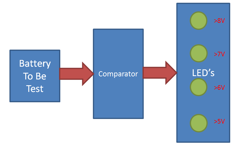
Suppose if testing battery’s voltage is greater than 8.0 Volt then all four LEDs will Glow. It means battery standing in good stage. If battery’s voltage greater than 7.0 Volt and less than 8.0 Volt then Last three LED’s will Glow and first LED will be OFF. It means battery standing in moderate stage. If Voltage of battery is greater than 6.0 Volt and less than 7.0 Volt then First Two LEDs will go OFF and last two LEDs will Glow. If Voltage of battery is greater than 5.0 Volt and less than 6.0 Volt then first three LEDs will go OFF and last LED will Glow. It means Battery is LOW. And if Voltage of battery is less than 5 volt no LED will Glow and it means battery’s voltage is below 5 volt. We can assume that battery as discharged.
For demonstration of this project I have added an extra potentiometer to change testing battery’s voltage. And it's circuit diagram is shown below.


Hello.You have used LM 358 as your main IC.Can you tell me why only this IC and why not LM358A or some other IC similar to that?
Thanks